
Centrifugal clutch and electric vehicle gear-shifting drive hub with same

A technology of centrifugal clutch and overrunning clutch, which is applied in the field of electric vehicles, electric vehicle shifting drive hubs, clutches, and centrifugal clutches. It can solve the problems of inability to transmit loads and engagement, etc., and achieve convenient operation, stable performance, and compact structure. Effect

Inactive Publication Date: 2012-04-11
ZHEJIANG YUANBANG INTELLIGENT EQUIP CO LTD
View PDF9 Cites 28 Cited by
  • Summary
  • Abstract
  • Description
  • Claims
  • Application Information

AI Technical Summary

Problems solved by technology

[0005] Although the centrifugal clutch achieves transmission, it still has certain defects: the engagement of the clutch depends on the centrifugal force, so it cannot transmit a load greater than the rated torque
[0016] Although the gear-shifting driving hub of an electric vehicle with the clutch type output mechanism can realize that the hub can rotate freely when the driving motor stops working, the clutch assembly must be manipulated.
That is to say, it is necessary to constantly manipulate the clutch assembly to switch during use, which still has a lot of inconvenience in actual use.

Method used


Image

  • Centrifugal clutch and electric vehicle gear-shifting drive hub with same
  • Centrifugal clutch and electric vehicle gear-shifting drive hub with same
  • Centrifugal clutch and electric vehicle gear-shifting drive hub with same

Examples


Embodiment Construction

[0053] The following are specific embodiments of the present invention and in conjunction with the accompanying drawings, the technical solutions of the present invention are further described, but the present invention is not limited to these embodiments.

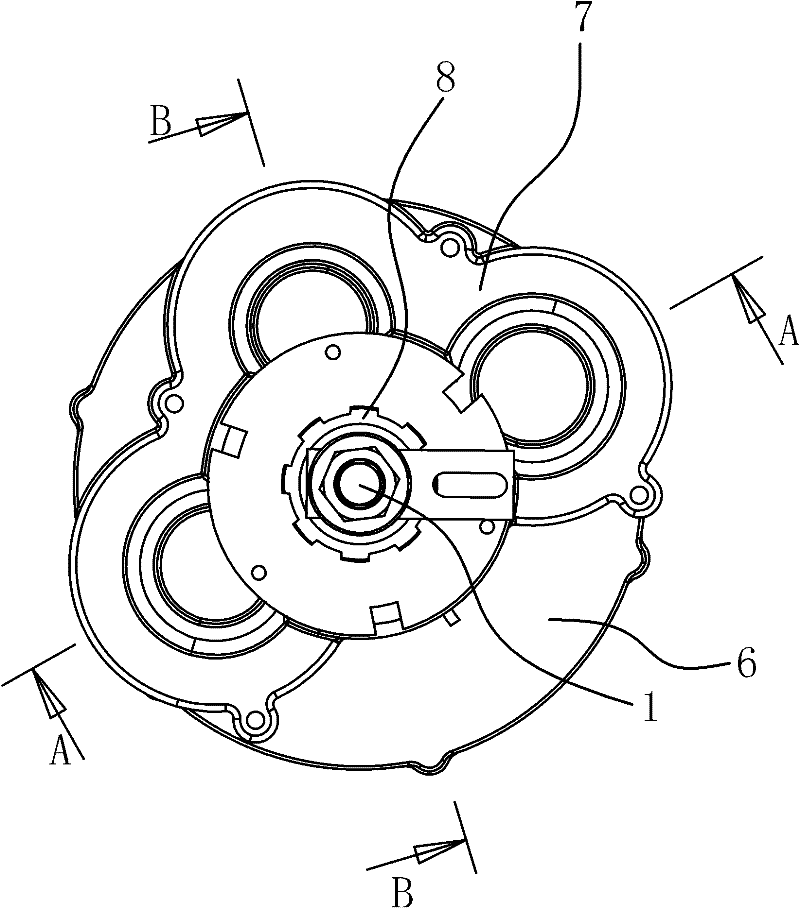
[0054] Such as Figure 7 to Figure 10 As shown, the centrifugal clutch 3 includes an input member 31, an output member 32, a ring gear 34, a pawl 36 and a reset mechanism.

[0055] Specifically, the input member 31 has a disc portion, and the output member 32 has a shaft portion. Therefore, the input member 31 can be a gear with teeth on the circumferential surface or a flywheel with a shaft portion and a disc portion; if the input member 31 is a gear, the teeth are engaged with the input device; The input device is connected. The output member 32 can be a shaft or a gear with a shaft portion. Such as Figure 7 to Figure 9 As shown, the solution provided in this embodiment is that both the input member 31 and the outpu...


PUM


Abstract

The invention provides a centrifugal clutch and an electric vehicle gear-shifting drive hub with the same, which belong to the technical field of machinery and vehicles. The invention solves the technical problem that conventional electric vehicles are inconvenient to back off. The centrifugal clutch comprises an input part and an output part, and the shaft of the output part is inserted in the axis of the disk of the input part; one side of the disk is provided with a gear ring and pawls in the gear ring, and the gear ring is firmly connected with the output part; the roots of the pawls are articulated with the side of the disk, and the inner wall of the gear ring is provided with ratchets; and restoring mechanisms are arranged between the pawls and the input part. The electric vehicle gear-shifting drive hub comprises a stator, a rotor, a hub body and a central shaft; an input gear shaft and an output gear shaft are sleeved on the central shaft, one end of the input gear shaft is firmly connected with the rotor, and one end of the output gear shaft is connected with the hub body; and an overrunning clutch and the centrifugal clutch are respectively connected between the other end of the input gear shaft and the other end of the output gear shaft. The invention has the advantages of stable transmission, convenience in use and the like.

Description

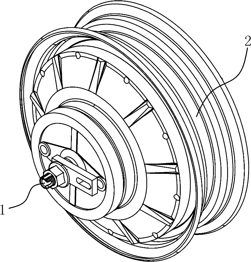
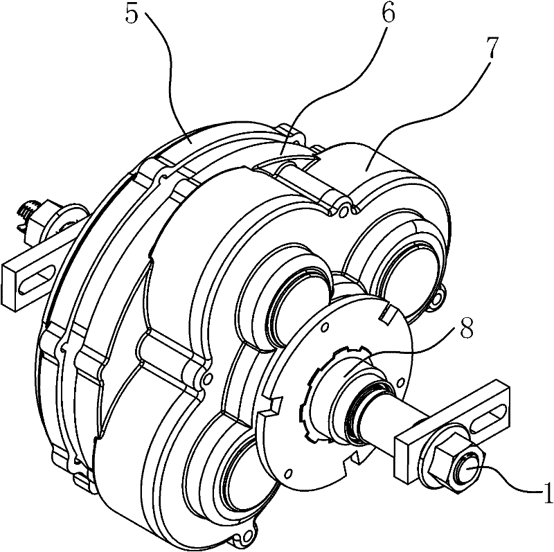
technical field [0001] The invention belongs to the technical field of machinery, and relates to a clutch, in particular to a centrifugal clutch. [0002] The invention also belongs to the technical field of vehicles, and relates to an electric vehicle, in particular to an electric vehicle shifting drive hub with the centrifugal clutch. Background technique [0003] The function of the one-way clutch is to make a certain element only rotate in a certain direction and lock in the other direction. When the power source drives the passive element, it can only transmit in one direction. If the power source changes direction (such as clockwise to counterclockwise), the passive element will automatically disengage from the function of not generating any power transmission. Such as overrunning clutches and centrifugal clutches. [0004] There are also many documents about clutches, such as a centrifugal clutch disclosed in Chinese patent documents [application number: 20092002220...

Claims


Application Information

Patent Timeline
IPC IPC(8): F16D43/16F16D47/04B60B27/00B60K17/02B60K17/04
Inventor 周嘉麟李跃岩
Owner ZHEJIANG YUANBANG INTELLIGENT EQUIP CO LTD
Learn More