Line element

A technology of pipe fittings and fluid pipelines, applied in the field of pipe fittings, can solve the problems of pipeline fluid solidification, failure to maintain heating, failure to prevent solidification, etc., and achieve the effect of reducing the risk of damage

Inactive Publication Date: 2012-04-11
NORMA GERMANY GMBH
View PDF4 Cites 1 Cited by
  • Summary
  • Abstract
  • Description
  • Claims
  • Application Information

AI Technical Summary

Problems solved by technology

[0005] A problem with fluid lines filled with liquids in motor vehicles is that the fluid present in the lines can freeze, especially in winter, when the vehicle is parked for a longer period of time
However, the heating cannot be maintained for extended periods of time when the motor vehicle is parked
Therefore, solidification cannot be reliably prevented by heating

Method used


Image

  • Line element
  • Line element

Examples


Embodiment Construction

[0034] The particulars presented here are exemplary and used for illustrative discussion of embodiments of the invention only, and are presented to provide what is believed to be the most useful and understandable description of the principles and conceptual aspects of the invention. Regarding this point, there is no attempt to introduce the structural details of the present invention beyond the level required for a basic understanding of the present invention. Those skilled in the art can clearly understand how to implement the present invention in practice through the description and accompanying drawings. Several forms.

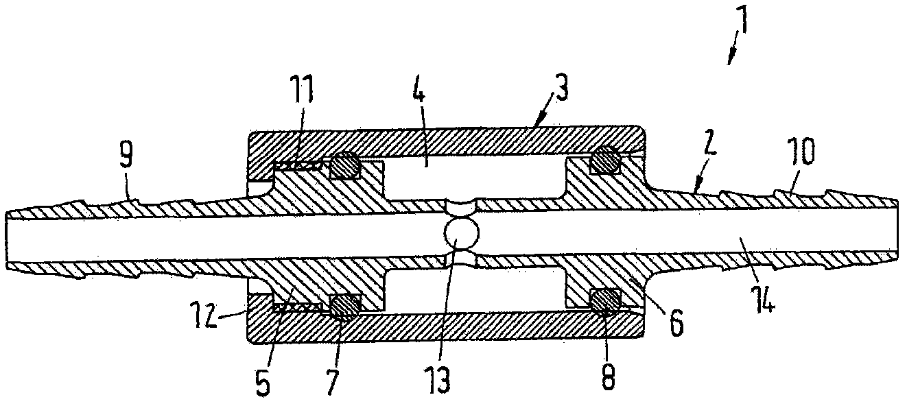
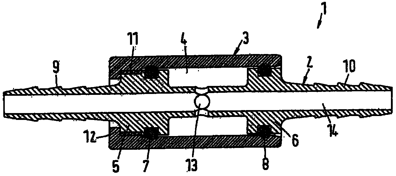
[0035] exist figure 1 A pipe fitting 1 with a fluid line 2 is shown in . The housing 3 surrounds the fluid line 2 in an annular manner, and an annular space 4 is implemented or formed between the housing 3 and the fluid line 2 . The annular space 4 is axially delimited by respective annular flanges 5 , 6 . The ring flanges 5 , 6 are integral with the f...


PUM


Abstract

Line element and method for forming a line element. The line element includes a fluid line, and a housing structured and arranged to surround the fluid line in a radially fluid-tight manner. An annular space is formed between the fluid line and the housing, which is filled at least in part with a compressible medium, and the fluid line has at least one opening inside the annular space.

Description

[0001] Cross References to Related Applications [0002] Pursuant to Title 35, United States Code, Section 119, this patent application claims priority to German Patent Application 102010045714.0, filed September 16, 2010, the disclosure of which is expressly incorporated herein by reference in its entirety. technical field [0003] The invention relates to a pipe with a fluid line and a housing. Background technique [0004] Pipes of this type are used, for example, in motor vehicles to convey engine coolant, or as so-called urea lines. For example, lines for supplying urea to help clean combustion engines are called urea lines. [0005] A problem in motor vehicles with fluid lines filled with liquid is that the fluid present in the lines can freeze, especially in winter, when the vehicle is parked for a longer period of time. For example, urea freezes at -11°C. [0006] Freezing of the liquid causes it to increase in volume, thus exerting a pressure load on the piping....

Claims


Application Information

Patent Timeline
Patent Type & Authority Applications(China)
IPC IPC(8): F16L55/054F01N3/10
CPCF16L57/02F16L55/02F01N2610/14F16L51/00Y10T29/49826F01P11/04F02M25/00F01N3/10
Inventor 安德烈亚斯·鲍尔马克·拉斯泰特斯蒂芬·曼恩帕特里克·塞梅尔
Owner NORMA GERMANY GMBH
Why Eureka
Try Eureka