Acoustic monitoring and location method for furnace tube leakage and device thereof
A positioning device and acoustic technology, applied in the direction of detecting the appearance of fluid at the leak point, indicating the working condition of the boiler, using liquid/vacuum for liquid tightness measurement, etc. Pipe leakage acoustic monitoring and other issues to achieve the effect of maintaining accuracy and improving positioning accuracy
Inactive Publication Date: 2012-04-11
NORTH CHINA ELECTRIC POWER UNIV (BAODING)
View PDF7 Cites 10 Cited by
- Summary
- Abstract
- Description
- Claims
- Application Information
AI Technical Summary
Problems solved by technology
[0004] Aiming at the shortcomings of the existing leakage measurement method mentioned in the above background technology, such as low precision and inability to monitor online, the present invention proposes a furnace tube leakage acoustic monitoring and positioning method and device
Method used
View moreImage
Smart ImageViewing Examples
Examples
example 1
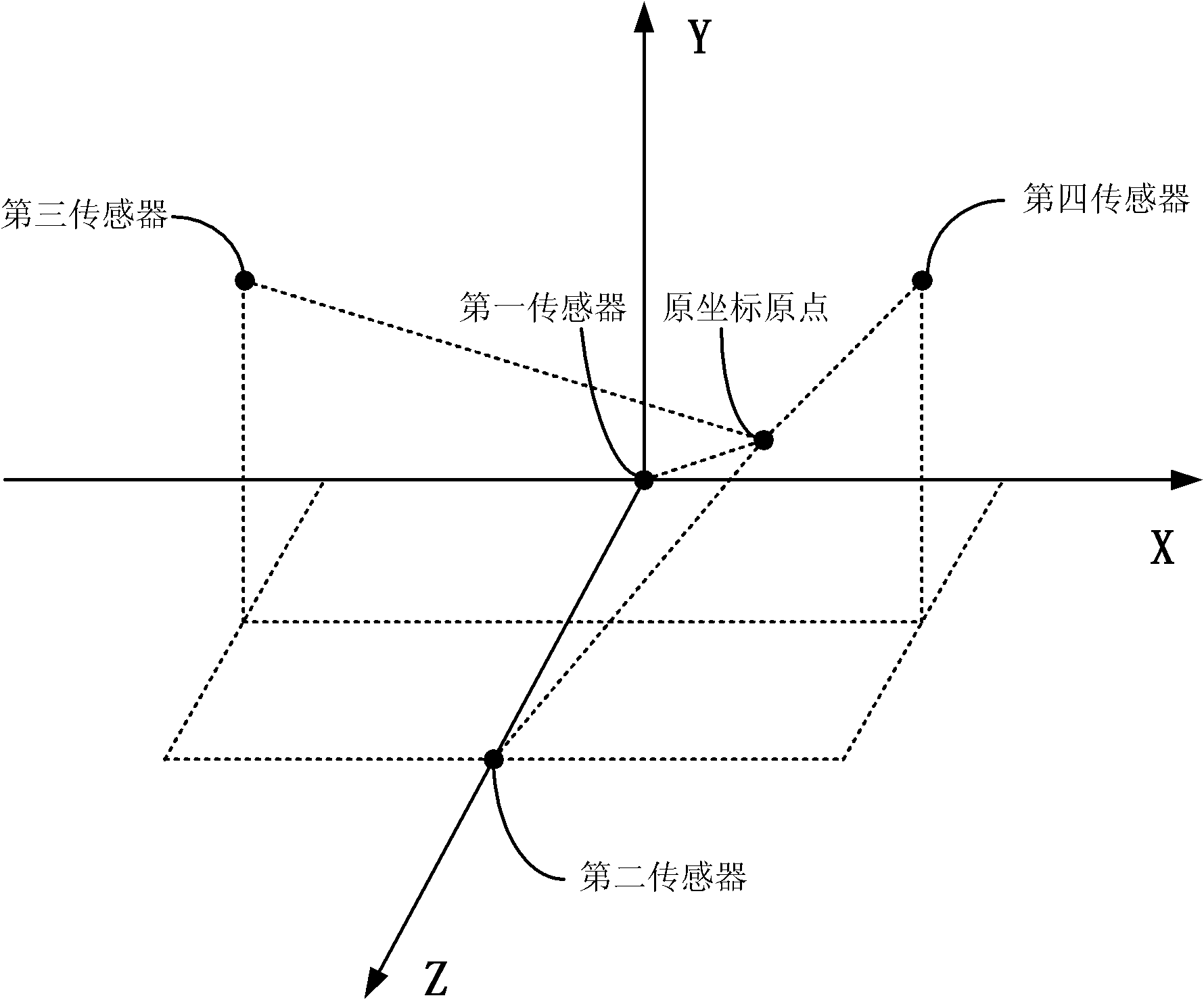
[0079] Example 1: When the delay error is 0 milliseconds, the positioning result is (3.0000, 2.0000, 3.0000)
example 2
[0080] Example 2: When the delay error is 1 millisecond, the positioning result is (2.7741, 2.1160, 2.8072)
example 3
[0081] Example 3: When the delay error is 0.1 milliseconds, the positioning result is (2.9752, 1.9964, 3.0372)
Login to View More PUM
 Abstract
The invention discloses an acoustic monitoring and location method for furnace tube leakage and a device thereof in the technical field of leakage location method in the boiler furnace. The invention can obtain hyperboloid equations of the leakage signal by measuring with a sensor; then the sensor having largest measured sound pressure level is selected as the reference sensor, so as to obtain the coordinate values of other sensors; then the leakage signal is filtered, and the time delay estimated values of other sensors and the reference sensor are obtained; finally, according to the coordinate value of each sensor, the CHAN algorithm is used for optimizing the hyperboloid equations, so as to further obtain the coordinate of the leakage point. The invention can select the reference sensor by the method of measuring sound pressure level, so as to avoid the problem that the negative time delay value of the theoretical values cannot be realized in actual measurement; three-dimensional location technology is adopted, the location accuracy is improved and the online monitoring and location are realized.
Description
technical field [0001] The invention belongs to the technical field of leakage positioning in a boiler furnace, and in particular relates to a furnace tube leakage acoustic monitoring and positioning method and device. Background technique [0002] Furnace pipe leakage of thermal power plant boilers seriously endangers the safe and economical operation of the power station. Existing technologies have been able to detect the leakage online when the furnace bursts, but most of them cannot be accurately located. The monitoring technology in patents US496079 and CN2253829 adopts the method of arranging a large number of measuring points on the wall of the furnace, which can only provide a rough positioning with the measuring points as the center and a radius of 10 meters. The patent CN101799533A has poor positioning accuracy and poor anti-disturbance ability. The algorithm in the patent CN101813545A requires a long iterative running time, and there are still accuracy problems, a...
Claims
Login to View More Application Information
Patent Timeline
 IPC IPC(8): F22B37/38G01M3/24
Inventor 安连锁沈国清冯强张世平王鹏
Owner NORTH CHINA ELECTRIC POWER UNIV (BAODING)
Features
- R&D
- Intellectual Property
- Life Sciences
- Materials
- Tech Scout
- Unparalleled Data Quality
- Higher Quality Content
- 60% Fewer Hallucinations
Learn More Browse by: Latest US Patents, China's latest patents, Technical Efficacy Thesaurus, Application Domain, Technology Topic, Popular Technical Reports.
© 2025 PatSnap. All rights reserved.Legal|Privacy policy|Modern Slavery Act Transparency Statement|Sitemap|About US| Contact US: help@patsnap.com


