Refrigerator

A technology for refrigerators and compressors, applied in household refrigerators, household refrigeration devices, defrosting and other directions, can solve the problems of compressor burden, reduced energy saving effect, and increased refrigerator temperature.

Inactive Publication Date: 2012-04-11
HITACHI APPLIANCES INC
View PDF5 Cites 5 Cited by
  • Summary
  • Abstract
  • Description
  • Claims
  • Application Information

AI Technical Summary

Problems solved by technology

[0006] However, in Patent Document 1, since the on-off valve is opened after the start-up of the compressor fails once, the load on the compressor is imposed, and the compressor cannot be started at an appropriate timing, causing the temperature inside the refrigerator to rise.
[0007] In addition, when the outside air temperature is high, if the on-off valve is opened when the compressor is stopped, the energy-saving effect of installing the on-off valve will be reduced.

Method used


Image

  • Refrigerator
  • Refrigerator
  • Refrigerator

Examples


Embodiment 1

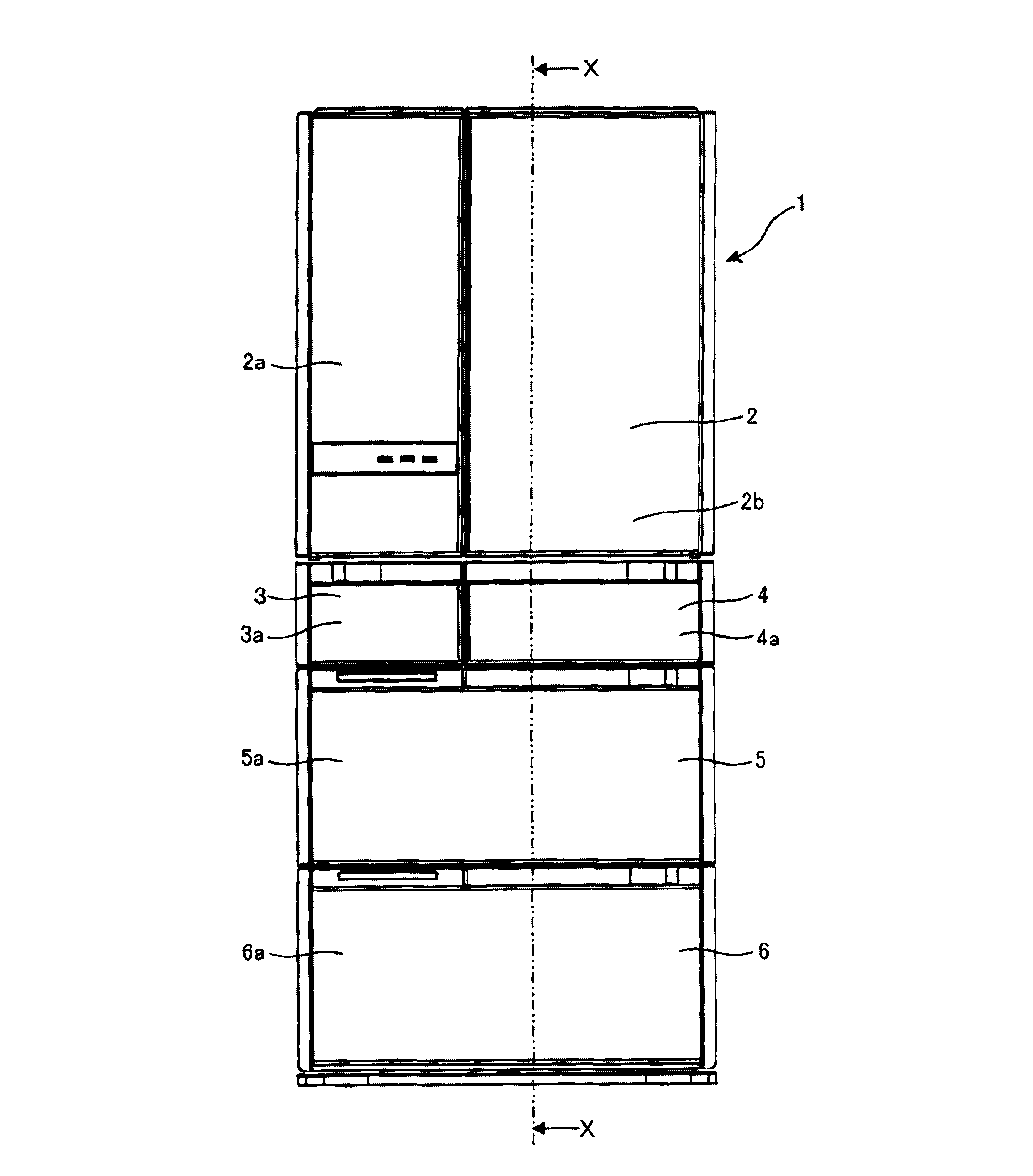
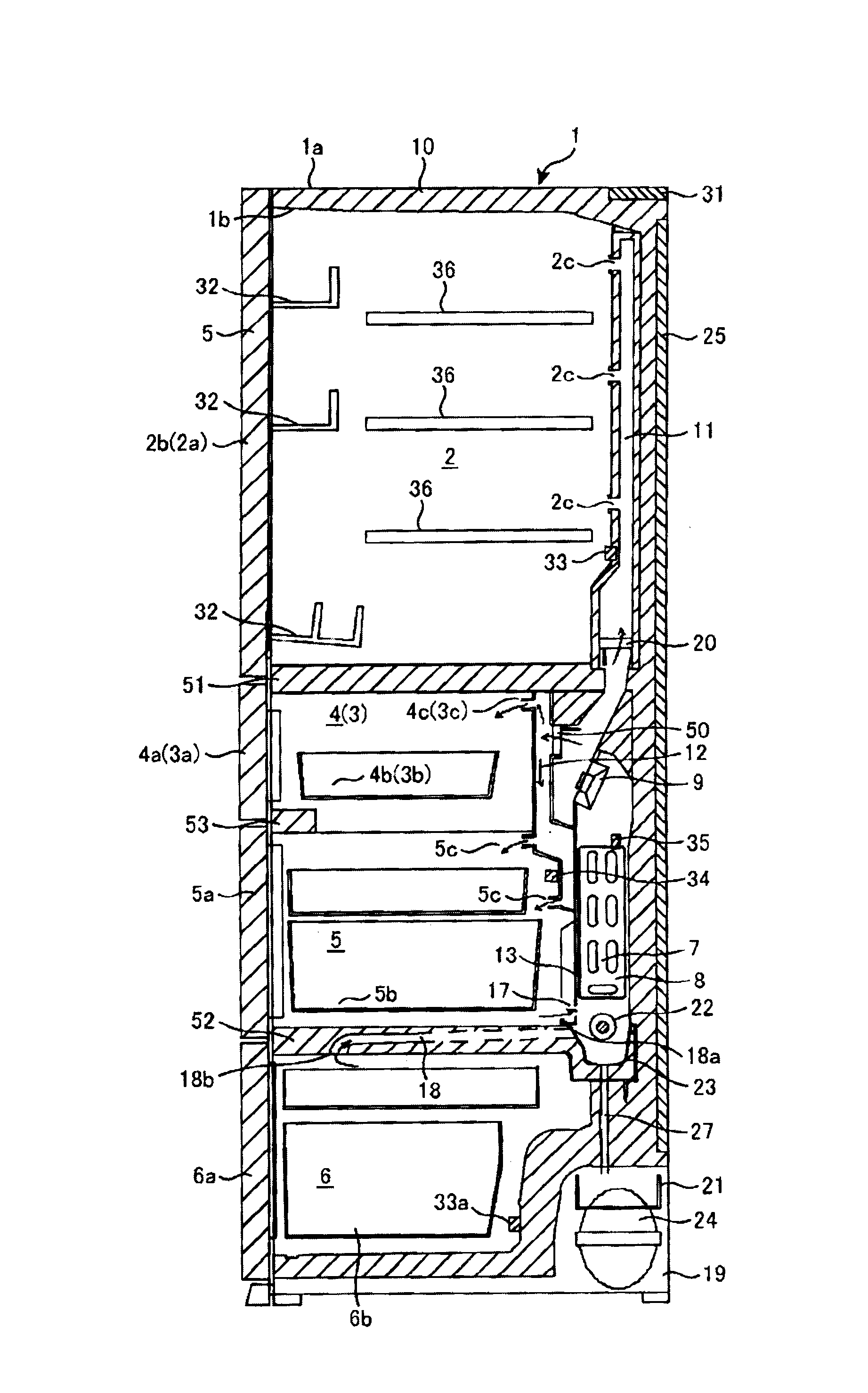
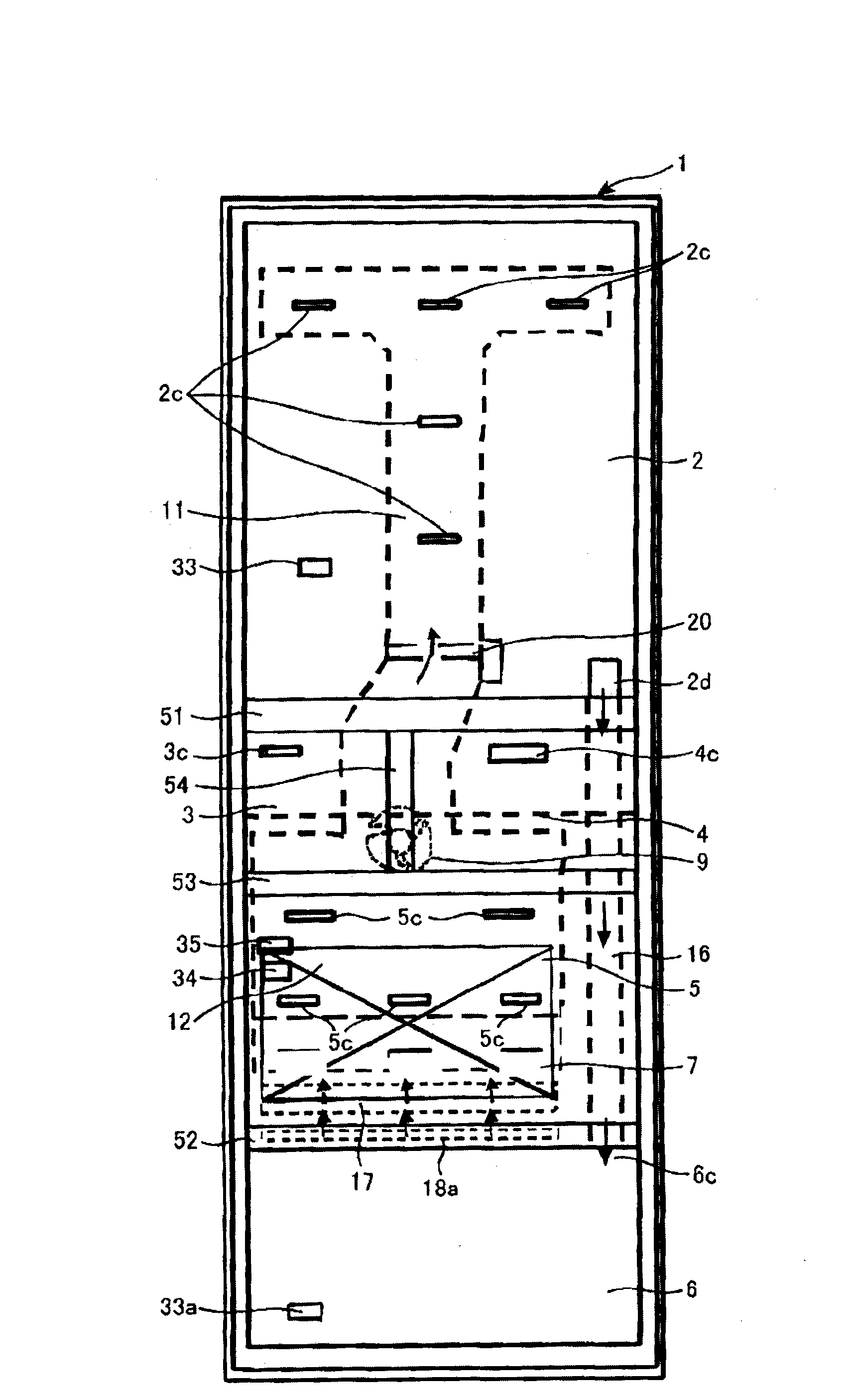
[0025] figure 1 It is a front external view of the refrigerator of this embodiment. figure 2 Indicates the inner structure of the refrigerator figure 1 X-X longitudinal section view in. image 3 It is a front view showing the interior structure of a refrigerator, and is a figure showing arrangement|positioning, etc. of a cold air duct and an air outlet. Figure 4 It is a figure which shows the structure of the refrigeration cycle of the refrigerator of 1st Embodiment.

[0026] Such as figure 1 As shown, the refrigerator main body 1 of the first embodiment has a refrigerator compartment 2, an ice making compartment 3, an upper freezer compartment 4, a lower freezer compartment 5, and a vegetable compartment 6 from above. In addition, ice making compartment 3 and upper freezer compartment 4 are arranged side by side between refrigerator compartment 2 and lower freezer compartment 5 . As an example, the refrigerator compartment 2 and the vegetable compartment 6 are storage ...

Embodiment 2

[0072] Next, refer to Figure 9 flow chart with Figure 10 The control of the refrigerator of the 2nd Embodiment of this invention is demonstrated with the time chart of.

[0073] exist Figure 9 In S201, the same as in Embodiment 1, if the refrigerator is cooled and cooled until the freezer temperature reaches the specified temperature T Foff , the compressor 24 is stopped after the valve 42 is closed and the high-pressure side and the low-pressure side of the refrigeration cycle are blocked.

[0074] In a forced circulation type refrigerator in which cold air is circulated in the refrigerator by the blower 9 or the like, frost adheres to the evaporator 7 as the compressor 24 operates. The frost adhering to the evaporator 7 after the cooling operation of the freezer has the energy to cool down to a low temperature. Therefore, when the compressor is stopped, the cooling energy of the frost is used to cool the refrigerator compartment. This is called frost cooling operatio...


PUM


Abstract

The invention aims at providing a refrigerator capable of improving reliability of startup of a compressor and high energy saving. The refrigerator is provided with: a compressor connecting and pressing a refrigerant via a pipe which the refrigerant passes by, a condenser making the refrigerant output from the compressor in heat dissipation, a decompression device decompressing the refrigerant output from the condenser, freezing circulation of an evaporator evaporating the refrigerant output from the decompression device and cooling air, and a refrigerant flow adjustment device disposed between the condenser and the evaporator, and controlling the refrigerant flow in a pipe. The refrigerator is provided with a pressure prediction device, the pressure prediction device predicts pressure at an intake side and an exhaust side of the compressor based on evaporator temperature, condenser temperature, and external air temperature when the compressor stops, rotation number before the compressor stops, and any time or combination of time passed after the compressor stops, via the pressure prediction device, whether startup of the compressor is allowed is determined by the pressure prediction device, and the compressor is started under the condition of pressure.

Description

technical field [0001] The present invention relates to refrigerators. Background technique [0002] As the background art of this technical field, there exists Unexamined-Japanese-Patent No. 2002-364937 (patent document 1). Patent Document 1 describes a refrigerator in which a low-pressure shell-type compressor, a condenser, a capillary tube, and an evaporator are sequentially connected to form a refrigeration cycle, and a refrigerator provided from the outlet of the condenser to the evaporator In the refrigerant flow passage between the inlets, an on-off valve for opening and closing the above-mentioned refrigerant flow passage; and the above-mentioned on-off valve is opened when the above-mentioned compressor is running, and the above-mentioned on-off valve is closed when the above-mentioned compressor is stopped. An on-off valve control device for controlling the on-off valve, wherein the on-off valve control device controls to open the on-off valve when the compressor ...

Claims


Application Information

Patent Timeline
Patent Type & Authority Applications(China)
IPC IPC(8): F25D11/02F25D29/00F25D21/06
CPCF25B49/022F25D17/045F25D17/08F25D29/00F25D2700/123F25D2700/14F25D2317/0681F25B41/22Y02B40/00
Inventor 小池畅志郎河井良二
Owner HITACHI APPLIANCES INC
Why Eureka
Try Eureka