
Fluorescence intensity correction method, fluorescence intensity calculation method, and fluorescence intensity calculation device and fluorescence intensity correction program

A technology of fluorescence intensity and correction method, which is applied in the field of fluorescence intensity correction procedures, can solve problems such as measurement errors, and achieve the effect of simple and accurate calculation

Active Publication Date: 2012-04-11
SONY CORP
View PDF7 Cites 9 Cited by
  • Summary
  • Abstract
  • Description
  • Claims
  • Application Information

AI Technical Summary

Problems solved by technology

If fluorescence leakage occurs, an error is created between the fluorescence intensity measured by each photodetector and the true fluorescence intensity from the target fluorochrome, causing measurement error

Method used


Image

  • Fluorescence intensity correction method, fluorescence intensity calculation method, and fluorescence intensity calculation device and fluorescence intensity correction program
  • Fluorescence intensity correction method, fluorescence intensity calculation method, and fluorescence intensity calculation device and fluorescence intensity correction program
  • Fluorescence intensity correction method, fluorescence intensity calculation method, and fluorescence intensity calculation device and fluorescence intensity correction program

Examples


Embodiment Construction

[0039] Hereinafter, preferred embodiments of the invention will be described in detail with reference to the accompanying drawings. In addition, the embodiments described below are representative examples of embodiments of the present invention, and the scope of the present invention should not be construed as being limited thereby. Here, description will be given in the following order.

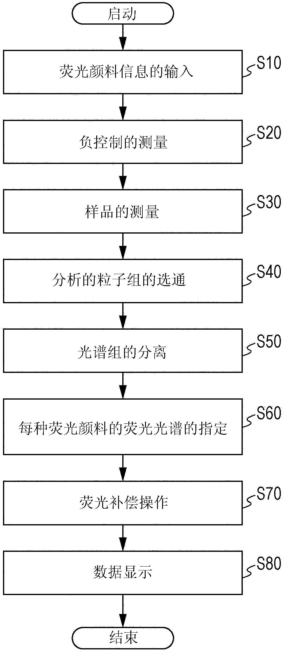
[0040] 1. Fluorescence intensity correction method

[0041] 1 Step S10: Input of fluorescent dye information

[0042] 2 Step S20: Measurement of Negative Control

[0043] 3 Step S30: Measurement of samples

[0044] 4 Step S40: Gating of analyzed particle groups

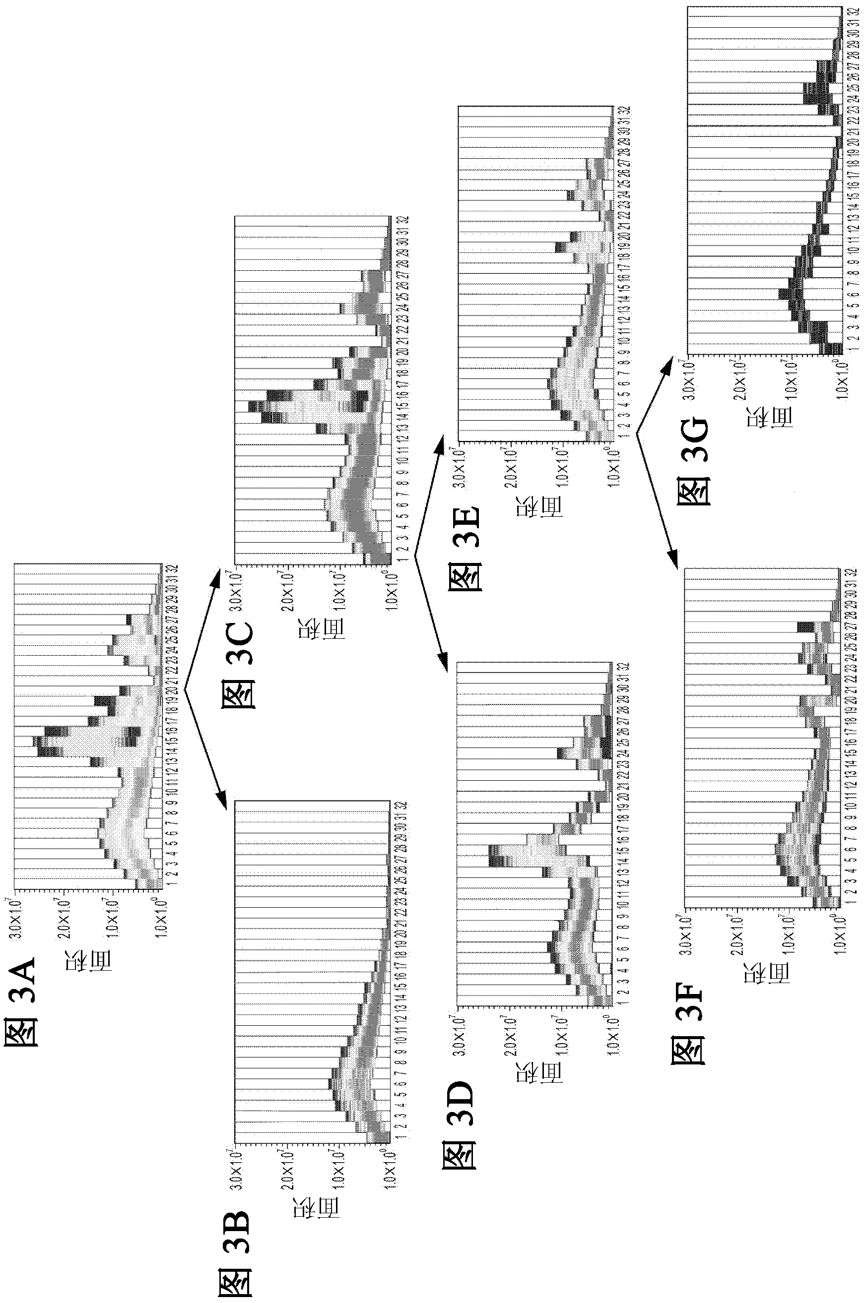
[0045] 5 Step S50: Separation into small spectral groups

[0046] 6 Step S60: specifying the fluorescence spectrum of each fluorescent dye

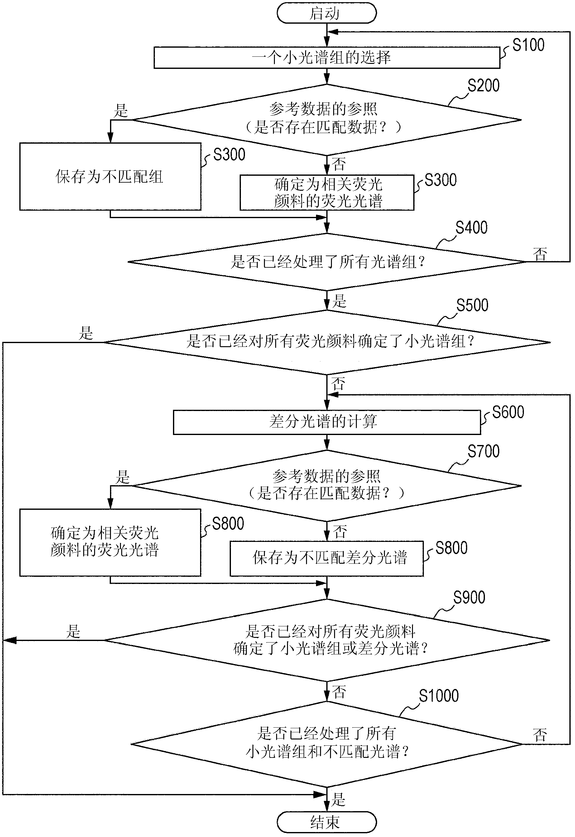
[0047] 6-1 Step S100: Selection of small spectral groups

[0048] 6-2 Step S200: Reference of reference data

[0049] 6-3 Step S300: Calculation of differential spectrum

[00...


PUM


Abstract

A fluorescence intensity correction method including: receiving fluorescence emitted from fluorescent pigments, collecting detected values from each light detector, and obtaining a fluorescence spectrum of each fluorescent pigment as one spectrum group; separating the obtained spectrum group into a plurality of small spectrum groups; comparing the separated small spectrum groups with a fluorescence wavelength distribution of each fluorescent pigment obtained in advance and specifying the small spectrum groups as the fluorescence spectrum of any fluorescent pigment; comparing a differential spectrum between small spectrum groups that are not specified and one or more specified small spectrum groups with the fluorescence wavelength distribution of unspecified fluorescent pigments obtained in advance, and specifying the differential spectrum as the fluorescence spectrum of any fluorescent pigment; and calculating the intensity of fluorescence emitted from each fluorescent pigment.

Description

technical field [0001] The invention relates to a fluorescence intensity correction method or a fluorescence intensity calculation method, a fluorescence intensity calculation device and a fluorescence intensity correction program. More specifically, the present invention relates to a fluorescence intensity correction method and the like for accurately calculating the fluorescence intensity emitted from each of a plurality of fluorescent dyes multiplex-labeled on microparticles. Background technique [0002] In the past, devices (for example, flow cytometers) that measure microparticle characteristics by labeling microparticles such as cells with fluorescent dyes and measuring the intensity and pattern of fluorescence emitted by the fluorescent dyes excited by laser irradiation have been used. In recent years, in order to analyze the characteristics of cells and the like in more detail, labeling microparticles with various fluorescent dyes and measuring light emitted from ea...

Claims


Application Information

Patent Timeline
Patent Type & Authority Applications(China)
IPC IPC(8): G01J3/30G01J3/46
CPCG01N21/274G01N21/6428G01N2021/6417
Inventor 酒井启嗣
Owner SONY CORP
Learn More