A lens test focusing machine

A focusing machine and lens technology, which is applied in optics, instruments, photography, etc., can solve the problems of affecting the viewing angle of the lens, occupying a large space, affecting the focusing results, etc., to achieve the effect of focusing processing and improving work efficiency.

Active Publication Date: 2015-08-05
珠海市运泰利自动化设备有限公司
View PDF4 Cites 0 Cited by
  • Summary
  • Abstract
  • Description
  • Claims
  • Application Information

AI Technical Summary

Problems solved by technology

The existing testing machine or focusing machine intelligently performs testing or focusing in a single way. If the lens needs to be continued to focus after testing, the lens needs to be moved from the testing machine to the focusing machine.
This not only wastes a lot of time, but also reduces work efficiency, and may cause positioning deviation of the lens when changing the working machine, and may also cause the lens to be scrapped due to scratches during the transfer process.
In addition to the above deficiencies, the size of the lens tested by the existing testing machine is above 8mm, and the lens size smaller than 8mm is mainly read by manual testing, and its testing efficiency and testing accuracy are low.
The existing focusing has the following defects due to technical limitations: the focusing ring is driven by a servo motor, which greatly increases the cost, makes the focusing machine itself expensive, and indirectly increases the cost of lens focusing; the servo motor and The focus ring is driven by the synchronous pulley and the synchronous belt, which takes up a lot of space, which affects the viewing angle of the lens during focusing and affects the focusing result

Method used


Image

  • A lens test focusing machine
  • A lens test focusing machine
  • A lens test focusing machine

Examples


Embodiment Construction

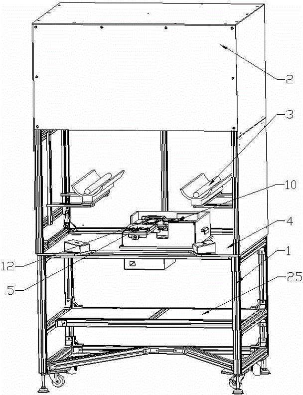
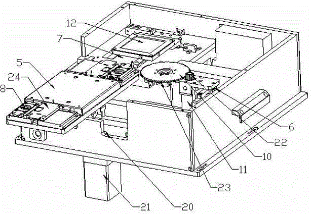
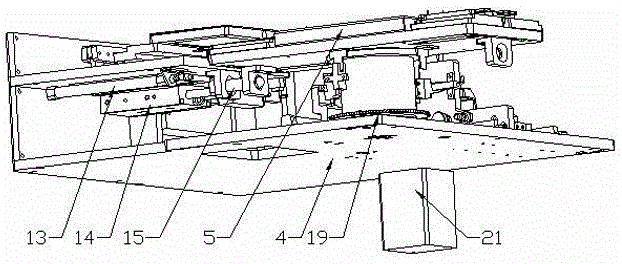
[0022] Such as Figure 1 to Figure 7 As shown, the present invention includes a frame 1, a light box 2, a focusing plate (not marked in the drawings) arranged in the light box 2, a light distribution lamp 3, a reference plate 4 and a peripheral host (not shown in the drawings). marked). A swing table 5 , an X-axis focusing table 6 , and a Y-axis test table 7 are arranged on the reference plate 4 . Two lens trays 8 are arranged diagonally on the oscillating table 5, and the oscillating table 5 can be rotated. A tray cover 24 is provided on the lens tray 8 . The X-axis focusing table 6 is driven by the X-axis cylinder 9 to reciprocate in the X-axis direction. A focusing ring 10 is provided on the X-axis focusing table 6 , and the focusing ring 10 is driven to rotate by a focusing motor 11 provided on the X-axis focusing table 6 . The focus ring 10 is arranged on a support cylinder (not marked in the drawings). A white screen 12 is arranged on the Y-axis test table 7 , and t...


PUM


Abstract

The invention discloses and provides a lens testing focusing machine, which has high automatic degree, high testing accuracy and high working efficiency. The lens testing focusing machine comprises a frame (1), a lamp box (2), a focusing plate, a light distribution lamp (3), a reference plate (4) and a peripheral host, wherein the reference plate (4) is provided with a swinging platform (5), an X-axis focusing workbench and Y-axis testing workbench; two lens trays are arranged at opposite angles on the swinging platform; the X-axis focusing workbench is driven by an X-axis cylinder to move in the X-axis direction in a reciprocating way; the X-axis focusing workbench is provided with a focusing ring (10); the focusing ring (10) is driven by a focusing motor arranged on the X-axis focusing workbench to rotate; the focusing ring (10) is arranged on a support cylinder; the Y-axis testing workbench is provided with a white screen (12); and the lens trays are provided with sensors. The lens testing focusing machine can be widely applied to the field of lens processing.

Description

technical field [0001] The invention relates to a lens test focusing machine. Background technique [0002] Lenses are used in more and more electronic products, such as mobile phones, cameras, video cameras, etc. After the lens is manufactured, the lens needs to be tested and focussed. During the testing process, it is necessary to test whether there are dead pixels in the manufactured lens, and whether the lens with dead pixels falls within the acceptable range. The existing testing machine or focusing machine intelligently performs testing or focusing in a single way. If the lens needs to be continued to focus after testing, the lens needs to be moved from the testing machine to the focusing machine. This not only wastes a lot of time, but also causes low work efficiency, and the positioning deviation of the lens may occur when the working machine is changed, and it may also cause the lens to be scrapped during the transfer process. In addition to the above deficiencie...

Claims


Application Information

Patent Timeline
Patent Type & Authority Patents(China)
IPC IPC(8): G03B43/00
Inventor 梁祖荣
Owner 珠海市运泰利自动化设备有限公司
Why Eureka
Try Eureka