
Traffic signal optimization method

An optimization method, technology for traffic signals

Inactive Publication Date: 2012-04-11
TSINGHUA UNIV
View PDF3 Cites 13 Cited by
  • Summary
  • Abstract
  • Description
  • Claims
  • Application Information

AI Technical Summary

Problems solved by technology

But its limitation is that, on the one hand, the complex and changeable real environment makes the pursuit of precise optimization algorithms not necessarily able to obtain the desired control effect; on the other hand, such algorithms often have high computational complexity, which limits the expansion of the scale of the problem.

Method used


Image

  • Traffic signal optimization method
  • Traffic signal optimization method
  • Traffic signal optimization method

Examples


Embodiment Construction

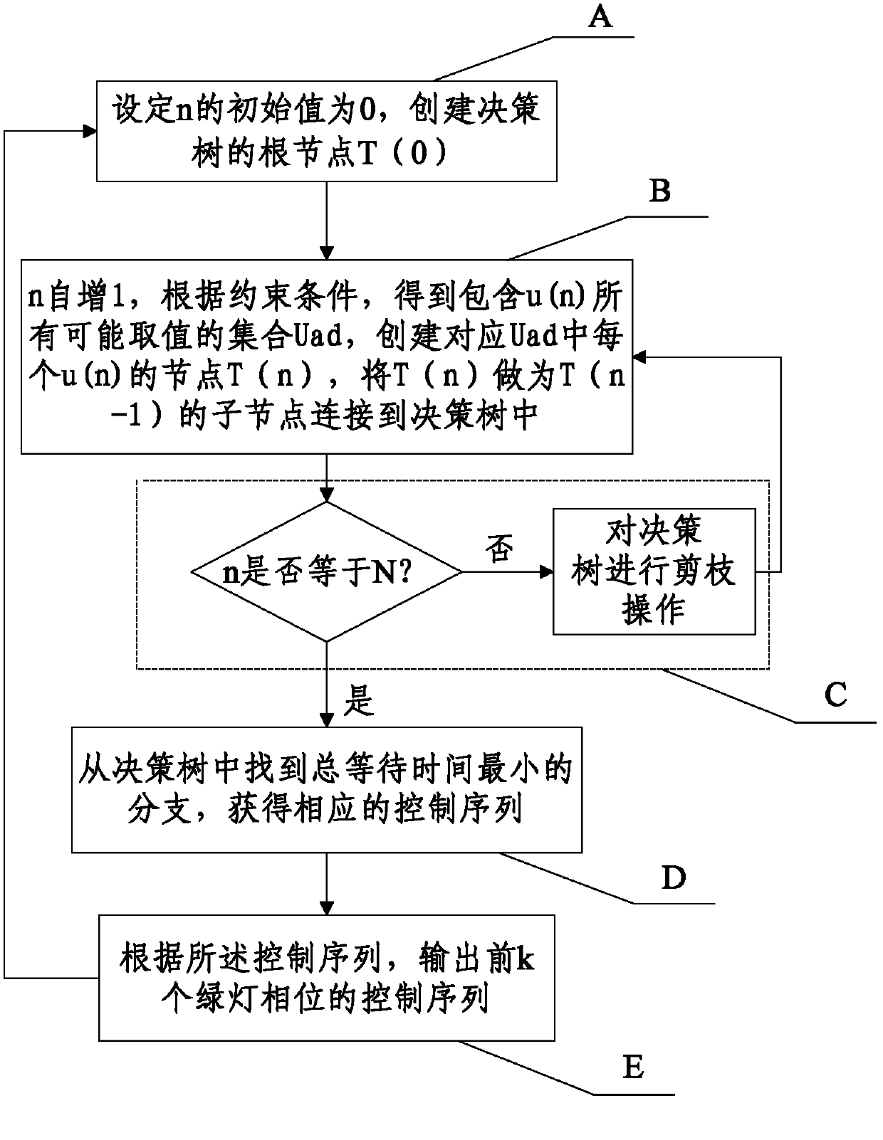
[0064] figure 1 It is a flow chart of the traffic signal optimization method described in the embodiment of the present invention. Such as figure 1 As shown, the method includes:

[0065] Step A: Set the optimization time window to include N minimum unit time periods T.

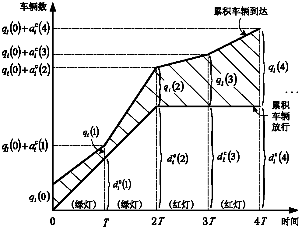
[0066] At the end of the nth T, the number of time periods T in which the signal light corresponding to the traffic flow i is continuously red or green is t i (n), determine whether the current is the first optimization time window, if so, set t i (0)=0, otherwise set t according to the execution result of the control sequence obtained in the previous optimization time window i (0).

[0067] When the nth T ends, the queue length of traffic flow i is q i (n), and set q according to the actual observation value i (0), the queue length is in units of the number of vehicles in the fleet.

[0068] Set the signal phase of the road intersection to u(n) within the nth T time, that is, u(n) determines the on-o...


PUM


Abstract

The invention discloses a traffic signal optimization method, and relates to the field of traffic signal control. The method comprises the following steps of: A: establishing a root node T(n) of a decision tree; B: self-increasing n by 1; and establishing a node T(n) corresponding to each u(n) in Uad according to constraint conditions, and connecting T(n) serving as a sub-node of T(n-1) to the decision tree; C: judging whether n is equal to N, if the n is equal to N, executing a step D, otherwise, performing pruning operation on the decision tree, and then executing the step B; D: finding outa branch with the minimum total waiting time from the decision tree to obtain a corresponding control sequence; and E: outputting a control sequence for previous k green light phases according to thecontrol sequence, and executing the step A. Through the traffic signal optimization method, the total waiting time of all vehicles at road crossings can be obviously shortened, meanwhile, since the pruning operation is performed on the decision tree, the method has controllable amount of calculation and is convenient to popularize.

Description

technical field [0001] The invention relates to the technical field of traffic signal control, in particular to a traffic signal optimization method. Background technique [0002] Traffic signal optimization methods at road intersections can be divided into two categories: offline optimization using historical data and online optimization using real-time vehicle information. The former is mainly timing control, while the latter can be further divided into two categories: non-model optimization methods and model-based optimization methods. In general, model-based optimization methods can achieve better optimization results. However, its limitation lies in that, on the one hand, the complex and changeable real environment makes the pursuit of precise optimization algorithms not necessarily able to obtain the desired control effect; on the other hand, such algorithms often have high computational complexity, which limits the expansion of the scale of the problem. Therefore, f...

Claims


Application Information

Patent Timeline
Patent Type & Authority Applications(China)
IPC IPC(8): G08G1/07G08G1/08
Inventor 王希勤李进源孟华东
Owner TSINGHUA UNIV
Learn More