
Blasting apparatus and method for blasting

A shot peening device and a technology for processed objects, which are applied in the direction of explosion generating devices, metal processing equipment, used abrasive processing devices, etc., can solve problems such as deterioration of the working environment and damage to the health of operators, and achieve the effect of maintaining accuracy

Inactive Publication Date: 2012-04-11
SHARP KK
View PDF6 Cites 10 Cited by
  • Summary
  • Abstract
  • Description
  • Claims
  • Application Information

AI Technical Summary

Problems solved by technology

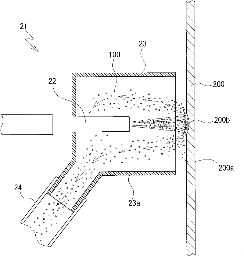
[0007] When the abrasive 100 is scattered around, there are negative effects such as deterioration of the working environment and damage to the health of the worker, so such abrasive 100 is recovered.

Method used


Image

  • Blasting apparatus and method for blasting
  • Blasting apparatus and method for blasting
  • Blasting apparatus and method for blasting

Examples


Embodiment Construction

[0030] Hereinafter, embodiments of the shot blasting apparatus and the shot blasting method of the present invention will be described in detail with reference to the drawings.

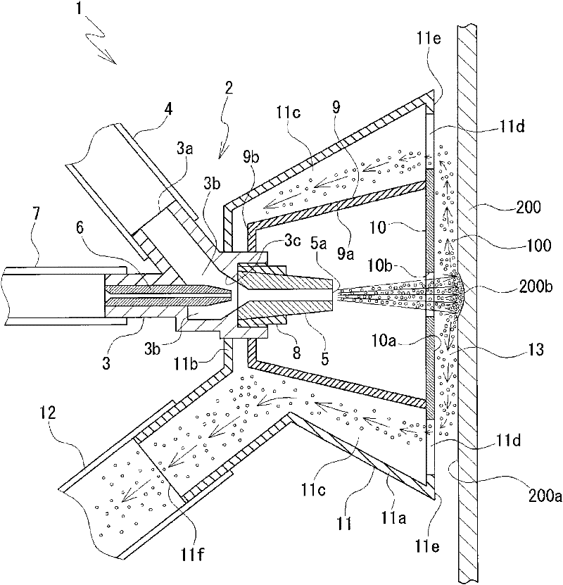
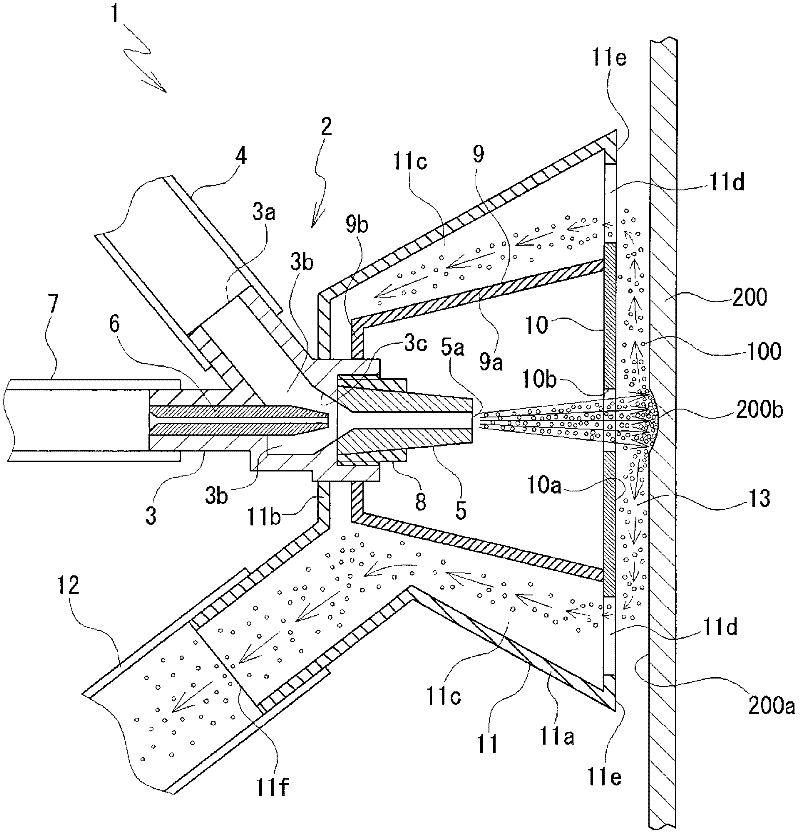
[0031] figure 1 It is a sectional view which shows the schematic structure of the shot blasting apparatus 1 of this invention. As shown in the figure, in the injection nozzle 2 that the shot blasting device 1 is equipped with, a substantially cylindrical container-shaped abrasive guide chamber 3b is formed in the nozzle body 3. The tank communicates with the abrasive inlet 3 a through the abrasive supply hose 4 to guide the abrasive 100 . A conical inner surface 3 c deep-drawn into a conical shape is formed at the front end portion of the abrasive guide chamber 3 b.

[0032] Moreover, the front-end|tip part of the air injection pipe 6 inserted from the rear of the abrasive guide chamber 3b is arrange|positioned inside the conical inner surface 3c. The air injection pipe 6 communicates with a compr...


PUM


Abstract

Provided is a blasting apparatus having an enhanced capacity of absorbing abrasives without affecting blasting of a work surface using abrasives. The blasting apparatus comprises a jet nozzle (2) capable of directing abrasives (100) to a surface (200a) of a work (200), a cover (10) having a current guide surface (10a) parallel to the surface (200a) of the work (200) and an opening (10b) for the abrasives (100) ejected from the jet nozzle (2) to pass through, a nozzle case (9) enclosing the jet nozzle (2) and the cover (10), and a recycling case (11) covering the nozzle case (9) to form a recycling path (11c) surrounding the nozzle for the abrasives (100) to recirculate therethrough by suction. The abrasives (100) ejected from the jet nozzle (2), after hitting the surface (200a) of the work (200), are recycled via a gap (13) formed between the current guide surface (10a) of the cover (10) and the surface (200a) of the work (200) through the recycling path (11c).

Description

technical field [0001] The present invention relates to, for example, an apparatus and method for processing the surface of a workpiece, and more specifically, to a blasting device and a blasting method for performing processing such as forming recesses on the surface of a workpiece such as a glass substrate by spraying abrasives. Background technique [0002] A glass substrate having a plate thickness of approximately 0.7 mm is generally used in flat display panels such as liquid crystal display panels and plasma display panels. It is desirable that such a glass substrate has a flat surface and good light transmittance. [0003] In such a glass substrate, defects such as fine scratches, air bubble holes, or air bubbles and foreign matter mixed in may occur on the surface during the manufacturing process. When such a defect occurs, there is a problem of scattering light. Therefore, after shaving off the portion, the concave portion formed by shaving off is usually filled wi...

Claims


Application Information

Patent Timeline
Patent Type & Authority Applications(China)
IPC IPC(8): B24C9/00B24C5/02
CPCB24C9/003B24C5/02
Inventor 吉泽武德泽井一辉
Owner SHARP KK
Learn More