Lower structure of vehicle

A vehicle and bending technology, which is applied in the field of vehicle substructure, can solve the problems of increasing the front bending stiffness of the front longitudinal beam, increasing the number of components, and increasing the stiffness, so as to improve the buckling strength, enhance the bending stiffness, and strengthen the The effect of intensity

Inactive Publication Date: 2012-04-11
TOYOTA JIDOSHA KK
View PDF6 Cites 3 Cited by
  • Summary
  • Abstract
  • Description
  • Claims
  • Application Information

AI Technical Summary

Problems solved by technology

[0004] However, in the underbody structure described in JP-A-2007-131148, the floor member and reinforcement are provided for the front side members, thus increasing the bending rigidity of the front portion of the front side members
Therefore, in order to increase the rigidity of the front portion of the main frame such as the front side member (floor member), the number of parts increases

Method used


Image

  • Lower structure of vehicle
  • Lower structure of vehicle
  • Lower structure of vehicle

Examples


Embodiment Construction

[0061] Hereinafter, embodiments of the present invention will be described with reference to the accompanying drawings. Note that in the description of the drawings, the same reference numerals denote similar components and repeated descriptions are omitted. In addition, for the convenience of illustration, the dimensional ratios of the drawings do not always coincide with those in the description.

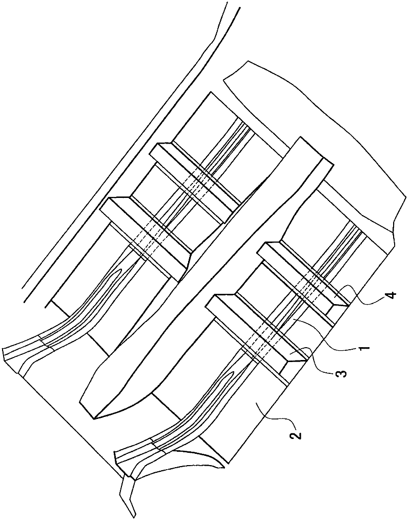
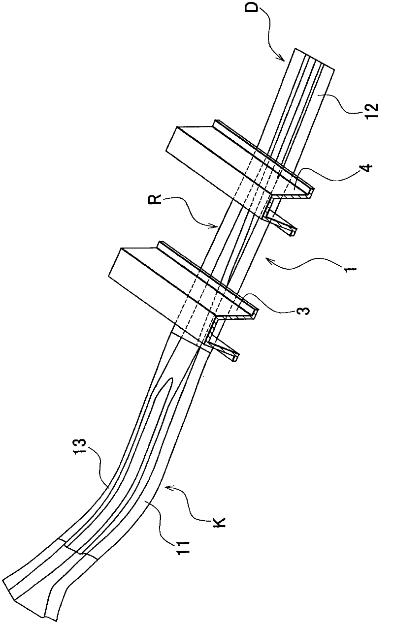
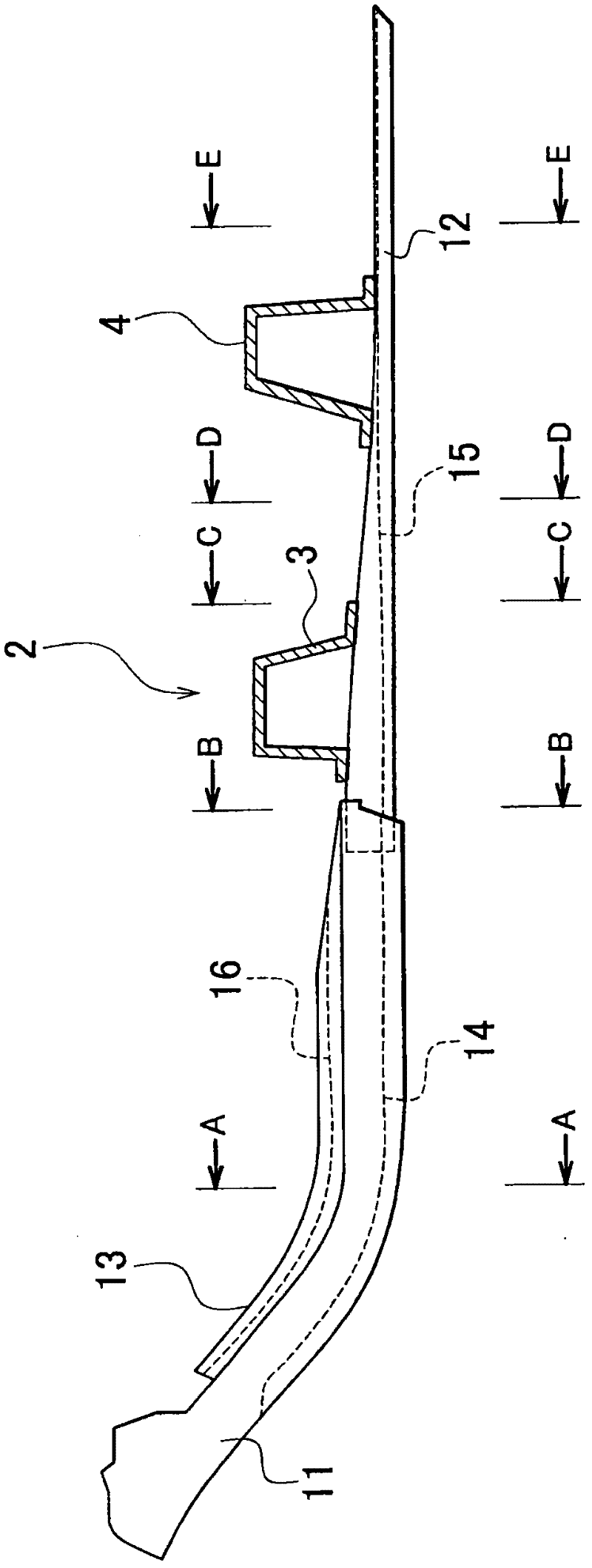
[0062] figure 1 is a perspective view of the lower structure of the vehicle according to the present embodiment. figure 2 is a perspective view of the floor component. image 3 is a side view of a floor member in the substructure of the vehicle. Figure 4A is along image 3 A cross-sectional view taken along line A-A in . Figure 4B is along image 3 A cross-sectional view taken along line B-B in . Figure 4C is along image 3 A cross-sectional view taken along line C-C in . Figure 4D is along image 3 A cross-sectional view taken along line D-D in . Figure 4E is alo...


PUM


Abstract

A floor member (1) includes a floor member front (11 ) arranged at a front side and a floor member rear (12) arranged at a rear side. A member rear upper (13) is mounted on the floor member front (11). The floor member front (11) and the floor member rear (12) respectively have a front upper bead (14) and a rear lower bead (15) that extend in a longitudinal direction of a vehicle.

Description

technical field [0001] The present invention relates to a lower structure of a vehicle, and more particularly to a lower structure of a vehicle including a joint between a floor and a main frame extending in the longitudinal direction of the vehicle. Background technique [0002] The substructure of a vehicle needs to absorb the loads applied in the event of a vehicle crash. As a load-absorbing structure, for example, Japanese Patent Application Laid-Open No. 2007-131148 (JP-A-2007-131148) describes a vehicle body underbody structure. In this vehicle body understructure, a floor is coupled to an upper portion of a front side member, and a floor upper member is provided at a turn-up portion, thus providing reinforcement inside the front side member. [0003] In this vehicle body substructure, the upper floor member is disposed above the front side members and provides reinforcement inside the front side members. Therefore, the upper vehicle body substructure can improve pro...

Claims


Application Information

Patent Timeline
Patent Type & Authority Applications(China)
IPC IPC(8): B62D25/20B62D21/10
CPCB62D25/20B62D21/10B62D21/00
Inventor 森健雄
Owner TOYOTA JIDOSHA KK
Why Eureka
Try Eureka