Rotor assembly

A component and rotor technology, applied in the field of rotor components, can solve problems such as poor bearing performance and difficulty in ensuring, and achieve the effect of increased life

Inactive Publication Date: 2012-04-11
DYSON TECH LTD
View PDF7 Cites 25 Cited by
  • Summary
  • Abstract
  • Description
  • Claims
  • Application Information

AI Technical Summary

Problems solved by technology

However, due to the buildup of tolerances associated with the path between the bearings, it would be difficult to ensure that both bearings are preloaded with forces to prevent slippage without being over loaded which would result in poor bearing performance

Method used


Image

  • Rotor assembly
  • Rotor assembly

Examples


Embodiment Construction

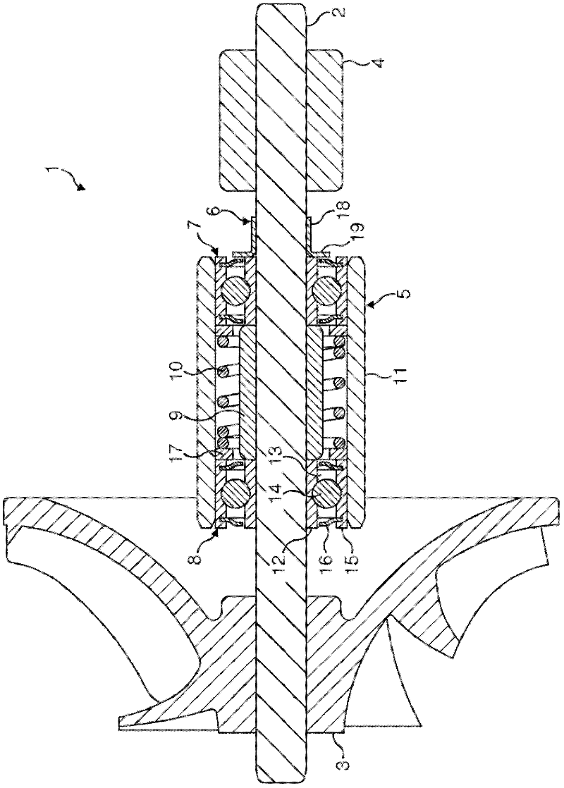
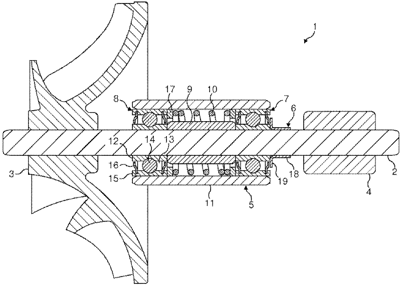
[0017] figure 1 The rotor assembly 1 includes a shaft 2, an impeller 3, a rotor core 4, a bearing cylinder 5 and a dust cover 6 are mounted to the shaft 2.

[0018] The impeller 3 is mounted to the first end of the shaft 2 . exist figure 1 The impeller 3 shown in is a centrifugal impeller. However, other types of impellers may equally be used depending on the intended application of the rotor assembly 1 .

[0019] A rotor core 4 is mounted to the second end of the shaft 2 . The rotor core 4 is formed of hard magnetic or soft magnetic material. The shaft 2 is formed of a soft magnetic material, which then reduces the reluctance of the magnetic circuit. However, a non-magnetic material could be used for the shaft 2 instead.

[0020] The bearing cartridge 5 is located between the impeller 3 and the rotor core 4 . The bearing cartridge 5 includes a pair of bearings 7 , 8 , a spacer 9 , a spring 10 and a sleeve 11 .

[0021] The bearings 7, 8 are identical, each comprising ...


PUM


Abstract

A rotor assembly (1) comprising a shaft (2) to which are mounted an impeller (3), a rotor core (4) and a bearing cartridge (5). The bearing cartridge (5) is mounted between the impeller (3) and the rotor core (4) and comprises a pair of bearings (7,8), a spring(10) that applies a preload to each of the bearings (7,8), and a sleeve (11) that surrounds the bearings (7,8).

Description

technical field [0001] The invention relates to a rotor assembly for a high speed compressor. Background technique [0002] The rotor assembly of many high speed compressors includes a shaft mounted to a housing by a pair of bearings, each bearing located at opposite ends of the shaft. Providing bearings at opposite ends of the shaft provides good stability. However, the path between the two bearings through the housing is quite long and typically traverses several different components of the compressor. Due to dimensional and geometric tolerances, it is often difficult to ensure that the rotor assembly can be precisely aligned within the housing. Additionally, for high speed compressors, the bearings are ideally preloaded to prevent slippage. However, due to the build-up of tolerances associated with the path between the bearings, it would be difficult to ensure that both bearings are preloaded with forces to prevent slippage without being over loaded, which would result...

Claims


Application Information

Patent Timeline
Patent Type & Authority Applications(China)
IPC IPC(8): F16C19/55F16C25/08F16C35/077F16C35/12H02K5/173F04D29/056
CPCF16C35/077F16C25/08F04D29/0563F04D29/059F16C19/55F16C35/12F16C19/06F16C19/54F16C25/083F16C2360/44F16C2380/26F01D25/162F04D29/0462F16C35/04F16C39/02F04D29/056
Inventor R.莫克里奇S.格里萨姆M.齐尔德
Owner DYSON TECH LTD
Why Eureka
Try Eureka