Cutting tool

A technology of cutting tools and sipes, which is applied to milling cutting blades, tools for lathes, milling cutters, etc., can solve problems such as overlapping of difficult positioning surfaces, deformation of fasteners, vibration of blades, etc., and improve the quality of the processed surface , Reduce blade deformation and prolong service life

Active Publication Date: 2013-06-12
ZHUZHOU CEMENTED CARBIDE CUTTING TOOLS CO LTD
View PDF3 Cites 1 Cited by
  • Summary
  • Abstract
  • Description
  • Claims
  • Application Information

AI Technical Summary

Problems solved by technology

Due to the sintering deformation of the blade, the clamping error of the tool and the blade, the processing error, the detection error and its assembly error, although the plane positioning surface of the cutter body and the blade can be processed into a plane with good flatness and high precision, but It is difficult to ensure that the corresponding positioning surfaces completely overlap. In order to ensure the impact resistance and dimensional stability of the cutting tool, it is generally preferred to ensure that the side near the upper bottom of the insert is in contact with the side of the sipe, that is, the angle between the side of the sipe and the bottom of the sipe is less than The angle between the side of the insert and the bottom of the insert
Although this structure solves the influence of the error of the cutting tool on the performance of the cutting tool to a certain extent, when the cutting tool bears a large load, the elastic deformation of the blade increases, and the side of the blade is inclined outward relative to the groove, resulting in the The side positioning surface of the body and the blade is separated, the clamping force can only be provided by the fastener, and the fastener must have a large deformation, which will cause a large vibration or even collapse of the blade

Method used


Image

  • Cutting tool
  • Cutting tool
  • Cutting tool

Examples


Embodiment Construction

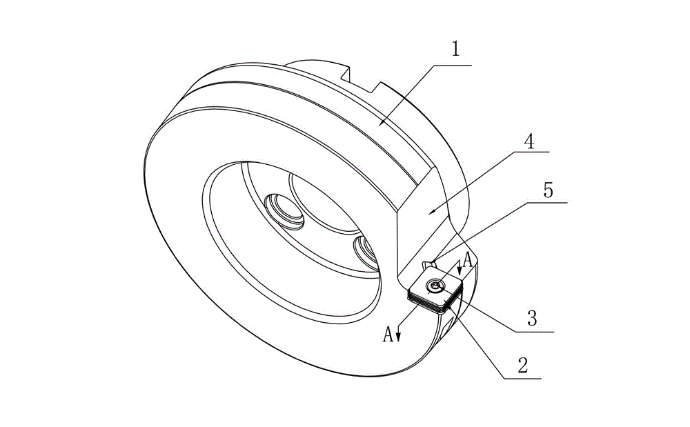
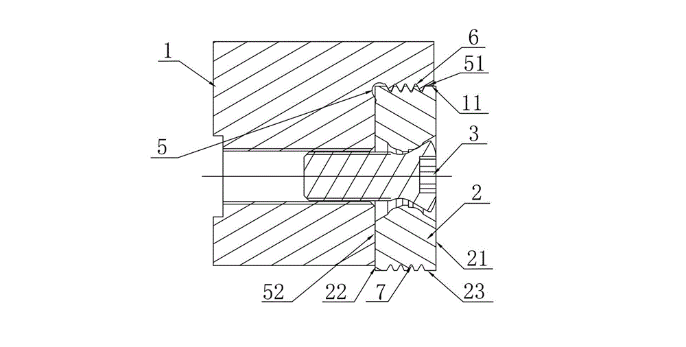
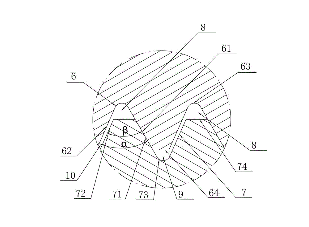
[0023] Figure 1 to Figure 3 A rotary cutting tool embodiment of the present invention is shown, the cutting tool includes a cutter body 1, a blade 2 and a fastener 3, the cutter body 1 is a cylindrical cutter body with its own central axis as the center of rotation, the cutter Body 1 is provided with a set of chip flutes 4 and sipes 5, cutter body 1 fixes blade 2 in sipes 5 through fasteners 3, sipes 5 are composed of sipes side 51 and sipes bottom 52, blade 2 It consists of an upper bottom surface 21, a lower bottom surface 22, and a side surface 23 connecting the upper bottom surface 21 and the lower bottom surface 22. There is an unevenness between the side surface 23 of the blade 2 and the side surface 51 of the sipe, which can prevent the side surface 23 from being inclined outward relative to the side surface 51 of the sipe. The matching structure makes the connection between the cutter body 1 and the blade 2 more compact and reliable. During the cutting process, the de...


PUM


Abstract

Disclosed in the present invention is a cutting tool comprising a cutter body (1), a cutter blade (2) and a fastener (3). The cutter body (1) is provided with at least one group of containing groove (4) and cutter slot (5). The cutter blade (2) is fixed in the cutter slot (5) by the cutter body (1) via the fastener (3). The cutter slot (5) is consisted of a side face (51) and a bottom surface (52). The cutter blade (2) is consisted of an upper bottom surface (21), a lower bottom surface (22) and a side face (23) connecting the upper bottom surface (21) and the lower bottom surface (22). A concave-convex matching structure is arranged between the side face (23) of the cutter blade (2) and the side face (51) of the cutter slot, to prevent the side face (23) from inclining outward from the cutter slot side face (51). The cutting tool has the advantages of effectively inhibiting vibration, improving anti-impact capacity, along with stable structure.

Description

technical field [0001] The invention relates to the field of metal cutting, in particular to cutting tools. Background technique [0002] Cutting tools are generally connected by means of planar contact between the cutter body and the side of the insert. The tool body and blade of this tool are easy to manufacture and easy to process; at the same time, when the side surface precision of the tool body and blade is high, the effective contact area can be increased, the transmitted torque can be improved, the impact resistance of the blade can be strengthened, and the dimensional accuracy of the cutting tool can be guaranteed. ;The large-area contact between the cutter body and the positioning surface of the blade can make the positioning surface of the blade only slightly deformed when the blade bears a large load, effectively ensuring the consistency of the dimensional accuracy of the cutting tool in the static state and during processing, and improving the cutting tool perfo...

Claims


Application Information

Patent Timeline
Patent Type & Authority Patents(China)
IPC IPC(8): B23D79/00B23B27/00
CPCB23B27/00B23C2200/128B23C5/2221B23D79/00B23C2210/168B23C5/06B23C5/2213
Inventor 江爱胜王社权刘敏易为
Owner ZHUZHOU CEMENTED CARBIDE CUTTING TOOLS CO LTD
Why Eureka
Try Eureka