
Automatic camshaft shifting device for tightening wrench

A technology of displacement device and camshaft, which is applied in the field of engine manufacturing and engine assembly automatic line to achieve the effect of saving energy, improving productivity and reducing the number of equipment

Active Publication Date: 2014-03-05
DALIAN ZHIYUN AUTOMATION
View PDF5 Cites 0 Cited by
  • Summary
  • Abstract
  • Description
  • Claims
  • Application Information

AI Technical Summary

Problems solved by technology

[0003] The technical problem to be solved by the present invention is: under the condition of not needing a pneumatic system, only one set of devices can be used to tighten bolts with different spacings of multiple varieties and single varieties at one station.

Method used


Image

  • Automatic camshaft shifting device for tightening wrench
  • Automatic camshaft shifting device for tightening wrench
  • Automatic camshaft shifting device for tightening wrench

Examples


Embodiment Construction

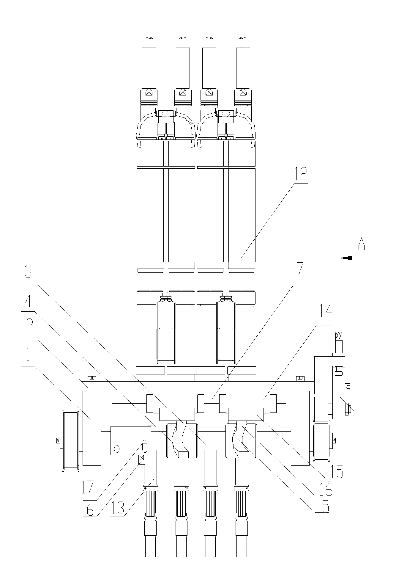
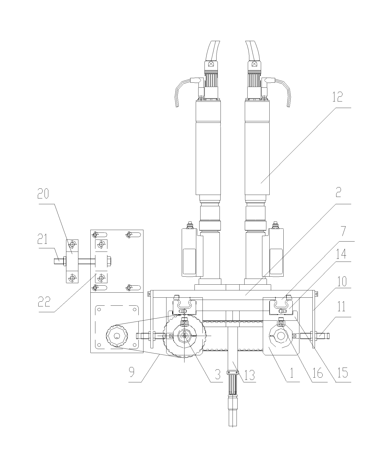
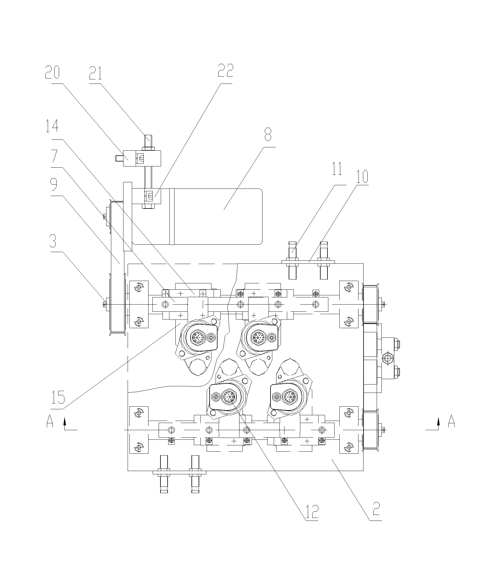
[0015] The present invention includes an upper support plate 2 fastened integrally with the support 1, and at least two camshafts 3 are installed in parallel in the support 1. At least two sections of cams 4 and one induction block 6 are arranged on the camshaft 3 . The induction block 6 can also be installed on the fixed ring 17, and the fixed ring 17 is installed on one end of the camshaft 3. The cam 4 is provided with a circumferential curved groove 5 . At least two linear guide rails 7 are respectively fixed on the lower surface of the upper support plate 2 and located above the camshaft 3 . The motor 8 is connected to one end of the camshaft 3 through a transmission belt 9, and the other end of the camshaft 3 is connected to one end of another adjacent camshaft through another transmission belt. An induction switch bracket 10 is installed on the upper support plate 2, and proximity switches 11 are respectively fixed on the bracket 10. The tightening shaft 12 and the ti...


PUM


Abstract

The invention relates to an automatic camshaft shifting device for a tightening wrench. The device comprises an upper support plate fastened with a support integrally, wherein at least two camshafts are parallelly arranged in the support; at least two sections of cams and an induction block are arranged on each camshaft; a circumferential curve groove is formed on each cam; at least two linear guide rails are fixed on the lower surface of the upper support plate and positioned above each camshaft; a motor is connected with one end of one camshaft through one driving belt, and the other end of one camshaft is connected with one end of the other camshaft adjacent to one camshaft through the other driving belt; a tightening shaft and the tightening wrench are fixed above and below a support plate; a sliding block which is in sliding fit with each linear guide rail is fastened with the support plate; and bumps are formed at the end of the support plate downwards and are inserted into the circumferential curve grooves on the camshafts. The whole device is not provided with pneumatic equipment, and only electric control is needed. The device has a simple and compact structure, and the number of equipment is reduced while functions are realized, so that production cost is reduced, the production rate is improved, and energy, field and fund are saved.

Description

technical field [0001] The invention relates to the field of engine manufacturing. Especially related to the field of engine assembly automatic line. Background technique [0002] On the automatic engine assembly line, ordinary tightening machine tools can only work separately if the bolt spacing is different when assembling tile covers of a single type of engine cylinder head, or when assembling tile covers of multi-variety cylinder heads. Tighten the bolts with different spacing. In this way, each station must be equipped with a tightening shaft and a tightening wrench, which increases the number of equipment installed and increases the production cost. The increase of stations also occupies the limited space of the production workshop, and also increases the man-hours required for the production of the whole line. In this type of tightening machine displacement device, it can only be driven by a cylinder as a power source. The cylinder drive requires the control of ai...

Claims


Application Information

Patent Timeline
Patent Type & Authority Patents(China)
IPC IPC(8): B23P19/06
Inventor 李萍邸彦召李维许晓敏
Owner DALIAN ZHIYUN AUTOMATION
Learn More