Shaft furnace with central air distribution device and method for controlling air distribution capacity

A shaft furnace and gas distribution technology, applied in the direction of shaft furnaces, furnaces, furnace types, etc., can solve the problems of chaotic gas flow redistribution in shaft furnaces, reduce the service life of shaft furnaces, increase maintenance and repair costs, etc., and achieve easy on-site transformation, The effect of ensuring metallization rate and long service life

Inactive Publication Date: 2012-04-18
张昭贵
View PDF5 Cites 10 Cited by
  • Summary
  • Abstract
  • Description
  • Claims
  • Application Information

AI Technical Summary

Problems solved by technology

For example: the addition of two horizontal gas distribution pipes affects the downward flow of the charge; it causes serious confusion in the gas flow redistribution in the shaft furnace;

Method used


Image

  • Shaft furnace with central air distribution device and method for controlling air distribution capacity
  • Shaft furnace with central air distribution device and method for controlling air distribution capacity
  • Shaft furnace with central air distribution device and method for controlling air distribution capacity

Examples


Embodiment Construction

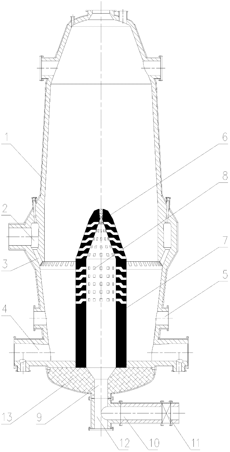
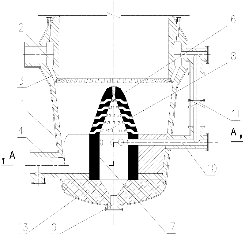
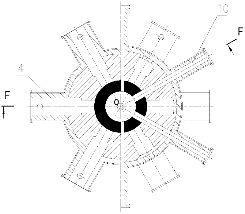
[0022] Such as figure 1 For Example 1. Such as figure 1 As shown, a shaft furnace with a central gas distribution device has at least a shell 1 with refractory materials, a gas header 2 embedded in the middle of the furnace body, and a circle of downward spouts 3 connected thereto. The lower part of the furnace body, the installation pipe 4 for installing the screw discharging device and the installation hole 5 for installing the screw loosening device. In the furnace, a tubular gas distribution device 7 with a conical top 6 is vertically erected in the central area of ​​the furnace bottom 13; on the side wall of the gas distribution device 7 and the conical top 6, several rows of small holes 8 are distributed to distribute the gas The space inside and outside the device 7 is connected, so that the reducing gas entering the inner space of the gas distribution device 7 can be distributed from the small hole 8 to the central area of ​​the shaft furnace. On part of the furnace...


PUM


Abstract

The invention provides a shaft furnace with a central air distribution device, which is characterized in that: a guide cone in the existing shaft furnace is heightened, hollowed-out and drilled, and a pipeline and an adjustable valve for conveying reducing coal gas into the interior of the furnace are additionally arranged outside the furnace, so that the implement method is simple, and the field renovation is easy. The air distribution device has the characteristics of small size, smoothness in blanking, uniformity in distribution of central coal gas and long service life. According to the invention, the coal gas amount of the center of the shaft furnace can be adjusted, and the metallization rate of the materials on the central part of the shaft furnace is ensured.

Description

technical field [0001] The invention relates to the technical field of non-blast furnace ironmaking, and relates to a shaft furnace used in a COREX process, in particular to a shaft furnace with a central gas distribution device and a method for controlling gas distribution in the center of the shaft furnace. Background technique [0002] The shaft furnace used in Baosteel Phase I COREX3000 is designed based on ZL98807174.6. Based on the traditional shaft furnace, the shaft furnace has changed the structure of the furnace bottom and added several spiral discharge devices. The structure of the spout. The coal gas entering the shaft furnace also all enters the furnace from the outer circumference of the shaft furnace through the downward spout. Because of this, as the diameter of the shaft furnace increases, the distribution of reducing gas in the center of the shaft furnace decreases gradually. Especially when the dust content of the gas increases and the gas permeability ...

Claims


Application Information

Patent Timeline
IPC IPC(8): C21B13/02
Inventor 张昭贵
Owner 张昭贵
Why Eureka
Try Eureka