
Concrete crack water plugging method

A technology for concrete and concrete reinforcement, applied in water conservancy projects, underwater structures, artificial islands, etc., can solve the problems of difficult pumping of cement slurry, re-seepage of cracks, labor and time-consuming drilling, etc., to achieve simple and easy construction operations. , The degree of water blocking is deep, and the effect of high durability

Active Publication Date: 2014-11-05
CHINA RAILWAY MAJOR BRIDGE ENG GRP CO LTD
View PDF6 Cites 0 Cited by
  • Summary
  • Abstract
  • Description
  • Claims
  • Application Information

AI Technical Summary

Problems solved by technology

[0004] Option (1) is only suitable for cracks with low water pressure and small water seepage; Option (2) is a method of drilling and grouting water plugging. Since the embedded depth of the grouting joint is shallow, the path of grout filling the cracks is from the outside to the Internally, in the process of grouting, the grout can only fill the surface of the crack, and cannot ensure that the grout penetrates into the depth of the crack, which will cause the repair of the crack to be insufficient to resist high water pressure. The water seepage part shifts or the cracks re-seep after water blocking occurs; the solution (3) is a traditional drilling grouting water blocking method, because the depth that the cement slurry can be injected is greater than that of the solution (2), so it can resist more Large water pressure, but in general, the width of the concrete crack is small, it will be difficult to pump the cement slurry. At the same time, it is labor-intensive to drill holes in the concrete wall, and it is difficult to install and fix the grouting pipe. The filling of pores around the wall cannot guarantee compactness, so the practicability of scheme (3) is not high

Method used


Image

  • Concrete crack water plugging method
  • Concrete crack water plugging method
  • Concrete crack water plugging method

Examples


Embodiment Construction

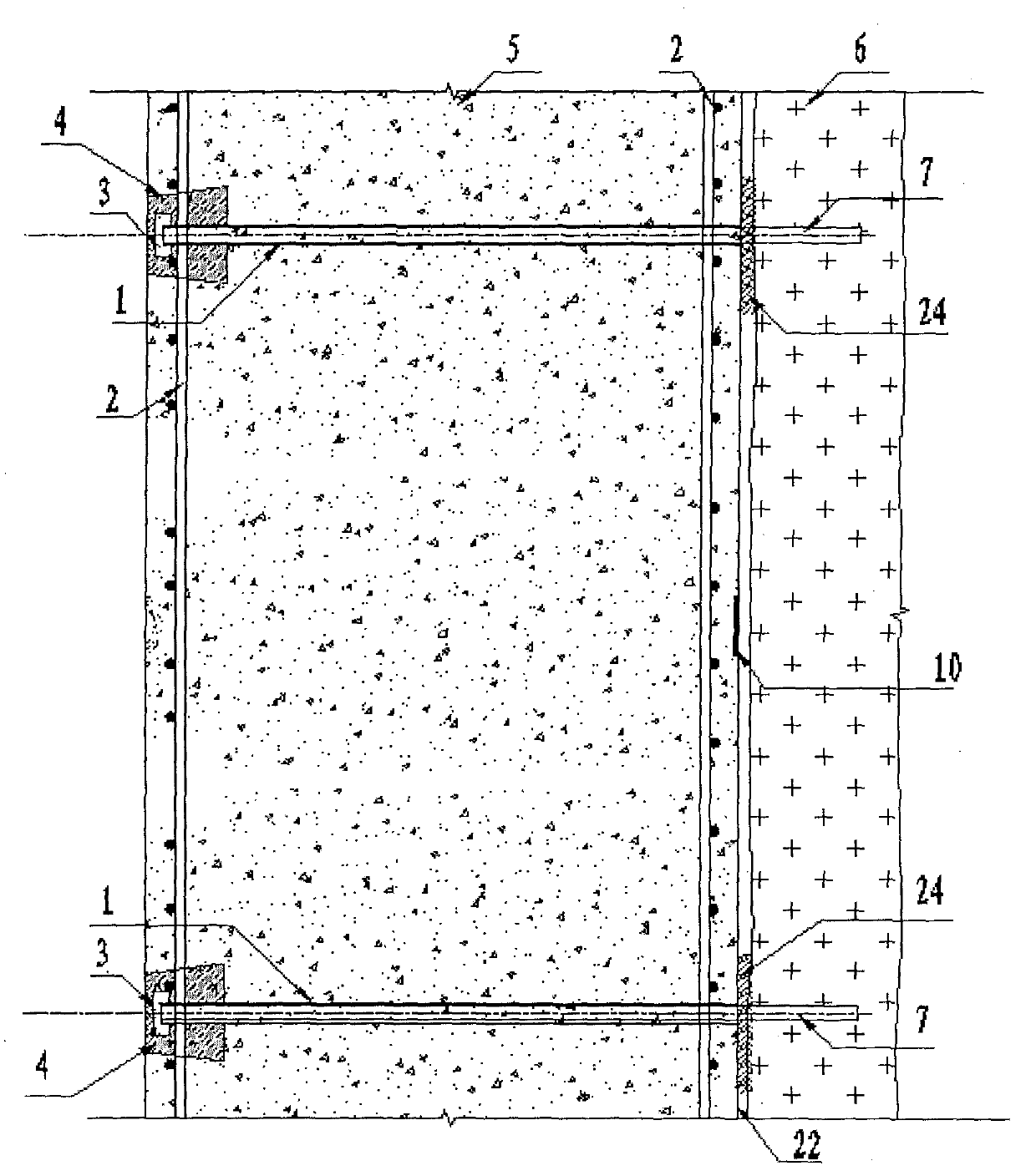
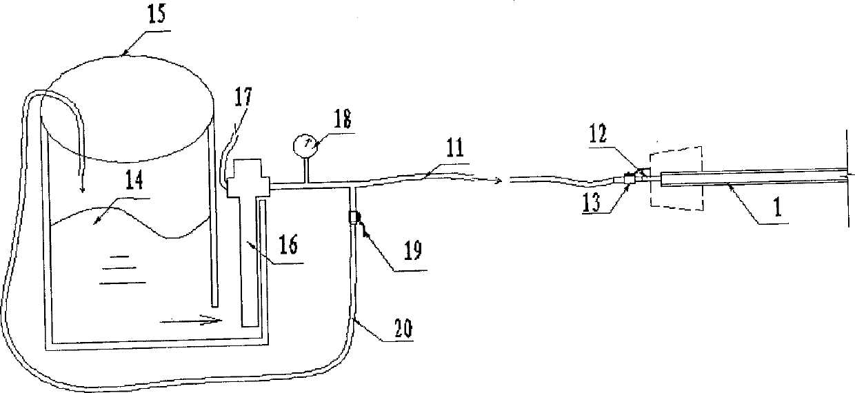
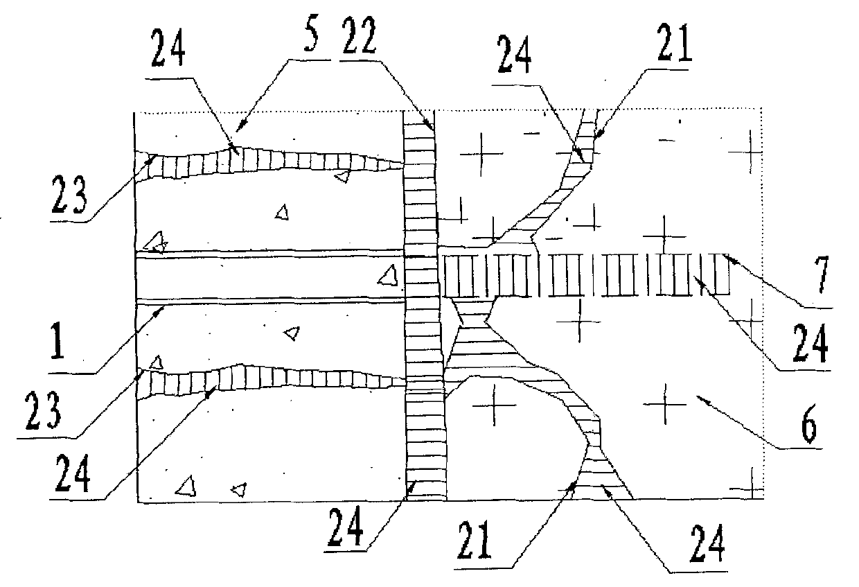
[0028] The present invention will be further described in detail below in conjunction with the drawings.

[0029] Please refer to figure 1 , The concrete crack water plugging device of the present invention includes a horizontally arranged grouting pipe 1 which penetrates the concrete 5. The length of the grouting pipe 1 is the vertical distance from the surface of the concrete 5 to the rock surface. In this embodiment, the grouting pipe has an outer diameter of 48 mm and a wall thickness of 3 mm. The grouting pipe 1 has a threaded button at one end, and a detachable end cap 3 is installed. After the grouting pipe 1 is fixed, the end cap 3 is tightened to prevent the concrete 5 from entering the grouting pipe during the concrete 5 pouring process 1. Block the grouting pipe 1. The end of the grouting pipe 1 with the end cap 3 is also provided with a pre-embedded wooden box 4, and the end of the grouting pipe 1 with the end cap 3 is accommodated in the pre-embedded wooden box 4.

...


PUM


Abstract

The invention discloses a concrete crack water plugging device. The concrete crack water plugging device comprises a grouting tube and a pre-buried wood box, wherein the grouting tube penetrates through concrete; one end of the grouting tube is provided with an end sealed cap; one end, provided with the end sealed cap, of the grouting tube can be connected with a grouting device; and one end, provided with the end sealed cap, of the grouting tube is accommodated in the pre-buried wood box. When the device is used for plugging water, cement grout is pressed into the grouting tube by using the grouting device and permeates into rock stratum cracks, gaps between concrete wall bodies and rock stratums, and concrete cracks to form a water plugging material.

Description

【Technical Field】 [0001] The invention relates to a method for blocking water by concrete cracks, in particular to a method for blocking water when a large-volume concrete structure of an underground engineering bears strong groundwater pressure. 【Background technique】 [0002] There are usually three conventional methods for blocking water from cracks in concrete structures: [0003] (1) The cracks are chiseled into a "V"-shaped groove with a certain depth and width, and the groove is filled and compacted with a quick-setting water blocking material. (2) Use a pneumatic drill to drill oblique holes on both sides of the crack, and the drill depth is half the depth of the structure. Embed the grouting joint in the drilled oblique hole, fix it firmly with cement, use fast instant cement to seal the crack surface tightly, and use a high-pressure grouting pump to inject chemical grouting material into the crack through the grouting joint to maintain a certain level Pressure, when pur...

Claims


Application Information

Patent Timeline
Patent Type & Authority Patents(China)
IPC IPC(8): E02D29/16
Inventor 刘斌吴汉斌
Owner CHINA RAILWAY MAJOR BRIDGE ENG GRP CO LTD
Learn More