
Handheld thermal infrared imager

An infrared thermal imager, handheld technology, applied in the field of infrared thermal imager, can solve the problems of complex structure, unclear imaging, image mismatch, etc., and achieve the effects of high dynamic range, clear imaging, and simple structure

Active Publication Date: 2013-10-30
UNIV OF ELECTRONICS SCI & TECH OF CHINA
View PDF3 Cites 0 Cited by
  • Summary
  • Abstract
  • Description
  • Claims
  • Application Information

AI Technical Summary

Problems solved by technology

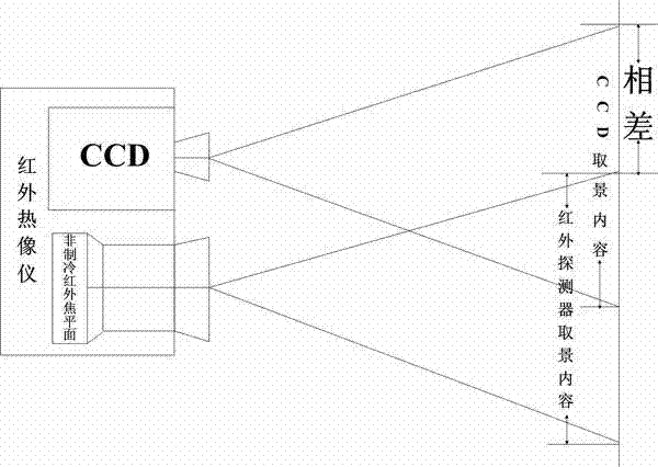
[0009] The purpose of the present invention is to solve the problem of information loss and image loss caused by the huge system, complex structure and high cost of the cooled infrared thermal imager, which cannot be popularized and applied on a large scale and the existence of a phase difference in the uncooled infrared focal plane handheld thermal imager. Problems such as low dynamic range of infrared images and unclear imaging caused by materials and technological levels

Method used


Image

  • Handheld thermal infrared imager
  • Handheld thermal infrared imager
  • Handheld thermal infrared imager

Examples


Embodiment 1

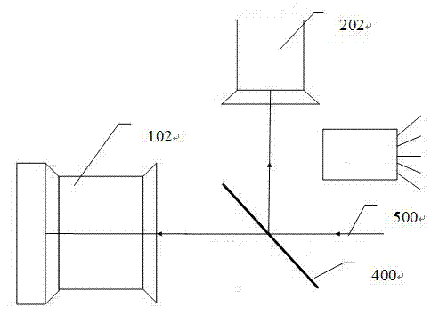
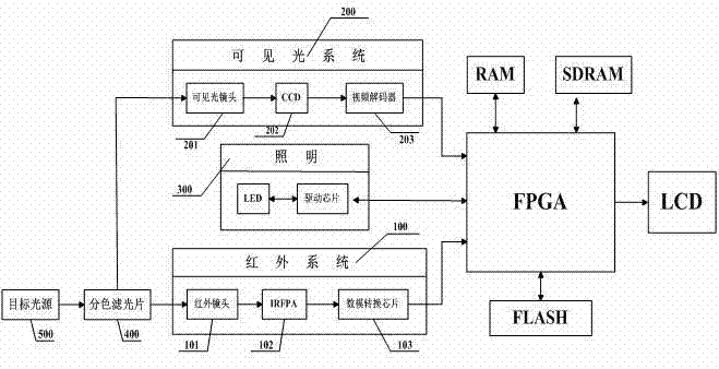
[0035] The coaxial optical path structure of the present invention requires that the light source emitted by the target must be received by the visible light photosensitive surface of the CCD and by the uncooled infrared focal plane at the same time, which requires a specific bandpass filter that separates visible light from far infrared light . As one of the preferred options: a dichroic filter with high transmittance of 8-14um infrared and high reflection of 0.4-0.7um of visible light is used. The dichroic filter uses germanium as a commonly used coating substrate, YbF 3 As a low-refractive-index film material, ZnS is used as a high-refractive-index film material. Using the design principle of long-wavelength interference cut-off filter, regular λ / 4 multilayer dielectric films are superimposed to obtain high visible light reflectivity; at the same time, the design of the film system, so that the far-infrared transmittance can also meet the requirements. After the target lig...

Embodiment 2

[0037] Since the minimum resolution of the human eye is about 0.5mrad. So the spatial resolution of the infrared system is greater than 0.5mrad. As one of the preferred options: the spatial resolution of the infrared system of the present invention is 1 mrad, and the uncooled infrared detector 102 adopts a 384×288 focal plane array (the size of the pixel is 35×35um, the field of view angle is 24°×18° ); the infrared lens 101 adopts a motorized focusing infrared lens with a focal length of 35mm.

Embodiment 3

[0039] In the present invention, the spatial resolution of the visible light system (200) should be proportional to the spatial resolution of the infrared system detection target of 1 mrad. The resolution is correspondingly 1mrad; when the ratio of visible light pixels to infrared image pixels is 1:4, the spatial resolution of the visible light system reaches 0.5mrad. As one of the preferred options: the visible light CCD 202 in the visible light system 200 adopts a 1 / 3-inch high-definition Sony CCD camera module (photosensitive area 4.8×3.6mm, effective pixel PAL: 752(H)×582(V)). The visible light lens 201 adopts a common photosensitive lens with a field angle of 60° and a focal length of 6mm, or a common photosensitive lens with a field angle of 30° and a focal length of 12mm.


PUM


Abstract

The invention discloses a handheld thermal infrared imager, comprising a color separation filter (400) for separating infrared light of 8-14 micrometers from visible light of 0.4-0.7 micrometer in a target luminous source, wherein the color separation filter (400) is arranged between an uncooled infrared detector (102) and the target luminous source (500), and the color separation filter (400), the uncooled infrared detector (102) and the target luminous source (500) coaxially constitute a coaxial light path structure on the same plane; and the target luminous source (400) reflects visible light to a charge-coupled device CCD (202) by using the color separation filter (400) and transmits infrared light to the uncooled infrared detector (102). By using the handheld thermal infrared imager, the problem of phase difference generated from paraxial light path detection of the conventional thermal imager is solved, and the defect that exterior images and visible light images can not be registered during short-distance tiny target detection is overcome.

Description

technical field [0001] The invention relates to an infrared thermal imager, specifically to a handheld infrared thermal imager. Background technique [0002] Various objects in nature exhibit a certain temperature, and the temperature of an object can often reflect its physical state. Any object with a temperature higher than absolute zero will produce infrared radiation, and the infrared radiation of an object is closely related to its surface temperature distribution. Therefore, the temperature of the surface of the object can be determined according to the corresponding relationship between the infrared radiation and the temperature by measuring the infrared radiation of the object. Generally, the higher the temperature, the stronger the infrared radiation. Compared with the contact method, this non-contact infrared radiation temperature measurement method has great advantages, for example, it can adapt to different measurement environments, and the temperature of the m...

Claims


Application Information

Patent Timeline
Patent Type & Authority Patents(China)
IPC IPC(8): G01J5/10G01J5/08
Inventor 刘子骥姜宇鹏辛勇明王然李伟
Owner UNIV OF ELECTRONICS SCI & TECH OF CHINA
Learn More