MEMS light valve, manufacture method thereof and display apparatus with MEMS light valve

A light valve and grating technology, applied in the field of display devices with the MEMS light valve, can solve the problems of large moving distance and high power consumption of the MEMS light valve

Active Publication Date: 2012-04-18
XIAN YISHEN OPTOELECTRONICS TECH CO LTD
View PDF5 Cites 15 Cited by
  • Summary
  • Abstract
  • Description
  • Claims
  • Application Information

AI Technical Summary

Problems solved by technology

[0006] The problem solved by the present invention is that the MEMS light valve in ...

Method used


Image

  • MEMS light valve, manufacture method thereof and display apparatus with MEMS light valve
  • MEMS light valve, manufacture method thereof and display apparatus with MEMS light valve
  • MEMS light valve, manufacture method thereof and display apparatus with MEMS light valve

Examples


no. 1 example

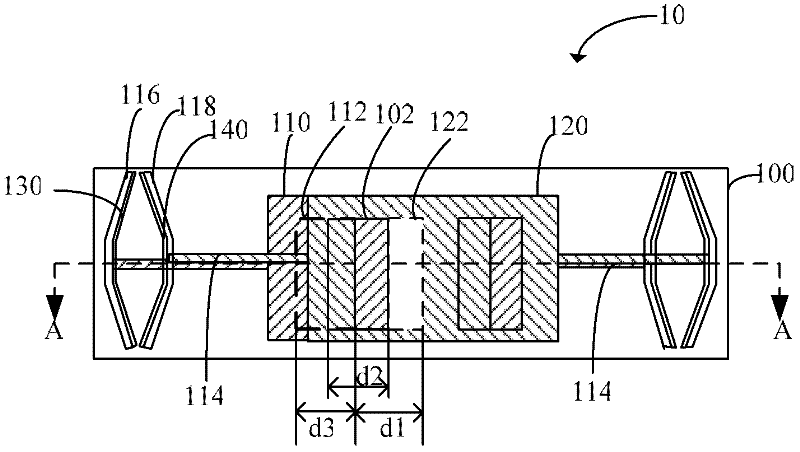
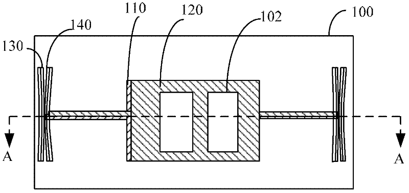
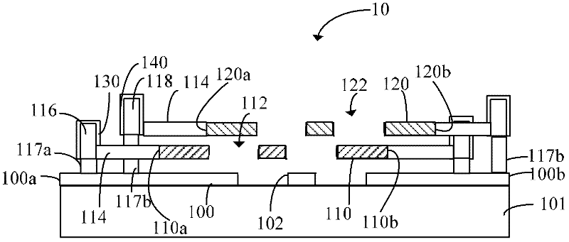
[0065] figure 1 is a schematic plan view of the opaque state of the MEMS light valve in the first embodiment of the present invention; figure 2 It is a schematic plan view of the light-transmitting state of the MEMS light valve in the first embodiment of the present invention; image 3 yes figure 1 The MEMS light valve shown along the figure 1 The schematic diagram of the cross-sectional structure in the A-A direction shown; Figure 4 yes figure 2 The MEMS light valve shown along the figure 2 The schematic diagram of the cross-sectional structure in the direction A-A is shown. Combine below Figure 1 to Figure 4 Specific examples of the present invention will be described.

[0066] combined reference Figure 1 to Figure 4 , the MEMS light valve of the present invention includes: a fixed grating 100, a first movable grating 110 and a second movable grating 120 stacked in layers; a first electrode 130, which is connected to the first movable grating 110; An electrode...

no. 2 example

[0083] Figure 6 is a schematic plan view of the MEMS light valve according to the second embodiment of the present invention. In the second embodiment, as Figure 6 As shown, the fixed grating 200 is circular and has a circle of openings on it. Of course, the openings can also be an array of openings arranged in an array along the circumference. In this embodiment, only one circle of openings is used. Take this as an example.

[0084] The first movable grating 210 is circular and stacked parallel to the fixed grating 200 . The first movable grating 210 has a plurality of openings 212 , and the openings of the first movable grating correspond to the openings of the fixed grating. The first movable grating 210 is correspondingly arranged above the fixed grating 200. The intersection points of the same diameter and the circumference of the first movable grating 210 are respectively connected with suspension rods 214. The suspension rods 214 are connected with the first elastic...


PUM


Abstract

The invention provides an MEMS light valve, a manufacture method thereof and a display apparatus with the MEMS light valve. The MEMS light valve comprises that: a fixed raster, a first movable raster and a second movable raster, wherein, the fixed raster, the first movable raster and the second movable raster are disposed in a laminated way; a first electrode which is connected with the first movable raster; a second electrode which is connected with the second movable raster. The first electrode and the second electrode are oppositely disposed. When the first electrode and the second electrode carry opposite charges, the first electrode and the second electrode move towards each other to get together, and the first movable raster and the second movable raster are driven to move towards each other to enable the fixed raster to be penetrable or impenetrable to light. According to a technical scheme of the invention, light transmission and light shielding speeds of the fixed raster can be accelerated, thus movement mileages of the first movable raster and the second movable raster needed for realizing switching between a light transmission state and a lightproof state of the light valve are reduced, power consumption needed for light valve state switching is reduced, and a switching speed is raised.

Description

technical field [0001] The invention relates to the field of display technology, in particular to a display device with a MEMS light valve, a manufacturing method thereof, and the MEMS light valve. Background technique [0002] In recent years, with the rapid development of the information and communication field, there is an increasing demand for various types of display devices. The current mainstream display devices mainly include: Cathode Ray Tube Display (CRT), Liquid Crystal Display (LCD), Plasma Display (PDP), Electroluminescent Display (ELD) and Vacuum Fluorescent Display (VFD). Due to the advantages of lightness, thinness, small footprint, low power consumption, and low radiation, liquid crystal display devices are widely used in various data processing equipment, such as televisions, notebook computers, mobile phones, and personal digital assistants. [0003] The liquid crystal display device mainly includes: a substrate, in which a backlight source is provided; p...

Claims


Application Information

Patent Timeline
IPC IPC(8): G02B26/02G09G3/34
Inventor 毛剑宏唐德明韩凤芹
Owner XIAN YISHEN OPTOELECTRONICS TECH CO LTD
Why Eureka
Try Eureka