Self-heating heat storage and cold storage air conditioning system and electric vehicle
A cold storage air conditioner and self-heating technology, applied in air conditioning systems, heating/cooling equipment, heating and refrigeration combinations, etc., can solve the problem of electric vehicles being unable to heat and cool, and achieve economic and social significance of good promotion and application value and time. , convenient way, the effect of short mileage
- Summary
- Abstract
- Description
- Claims
- Application Information
AI Technical Summary
Problems solved by technology
Method used
Image
Examples
Embodiment 1
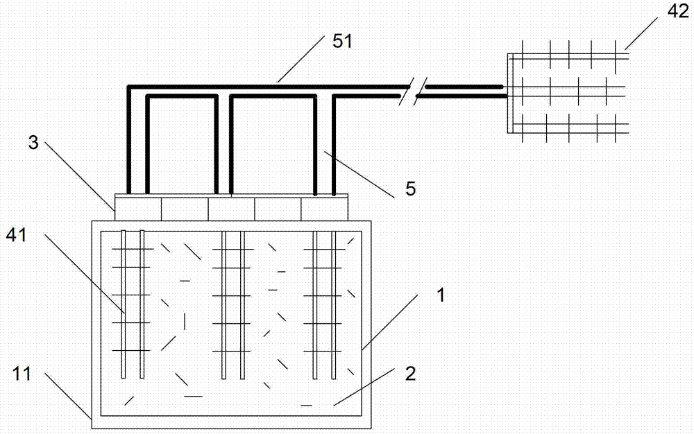
[0028] Such as figure 1 The air conditioning system shown, the system includes a storage tank 1 for storing cold and heat storage medium 2, and a heat pump device; one end of the heat pump device is placed in the storage tank 1, and the other end of the heat pump device is used to place the cold Or heat in the air circulation channel.
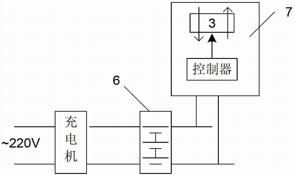
[0029] In this embodiment, the heat pump device adopts a semiconductor thermoelectric chip pumping device, and the semiconductor thermoelectric chip is a kind of "heat pump", which has a cold end and a hot end, so that heat is conducted between the hot end and the cold end, and through Controlling the current of the semiconductor thermoelectric chip can reverse the cold end and the hot end, and change the speed of heat conduction by controlling the voltage. The material of the semiconductor thermoelectric chip used in this embodiment is metal compound and its solid solution alloy, such as Bi2Te3 / Sb2Te3, PbTe, SiGe, CrSi and so on. The semicon...
Embodiment 2
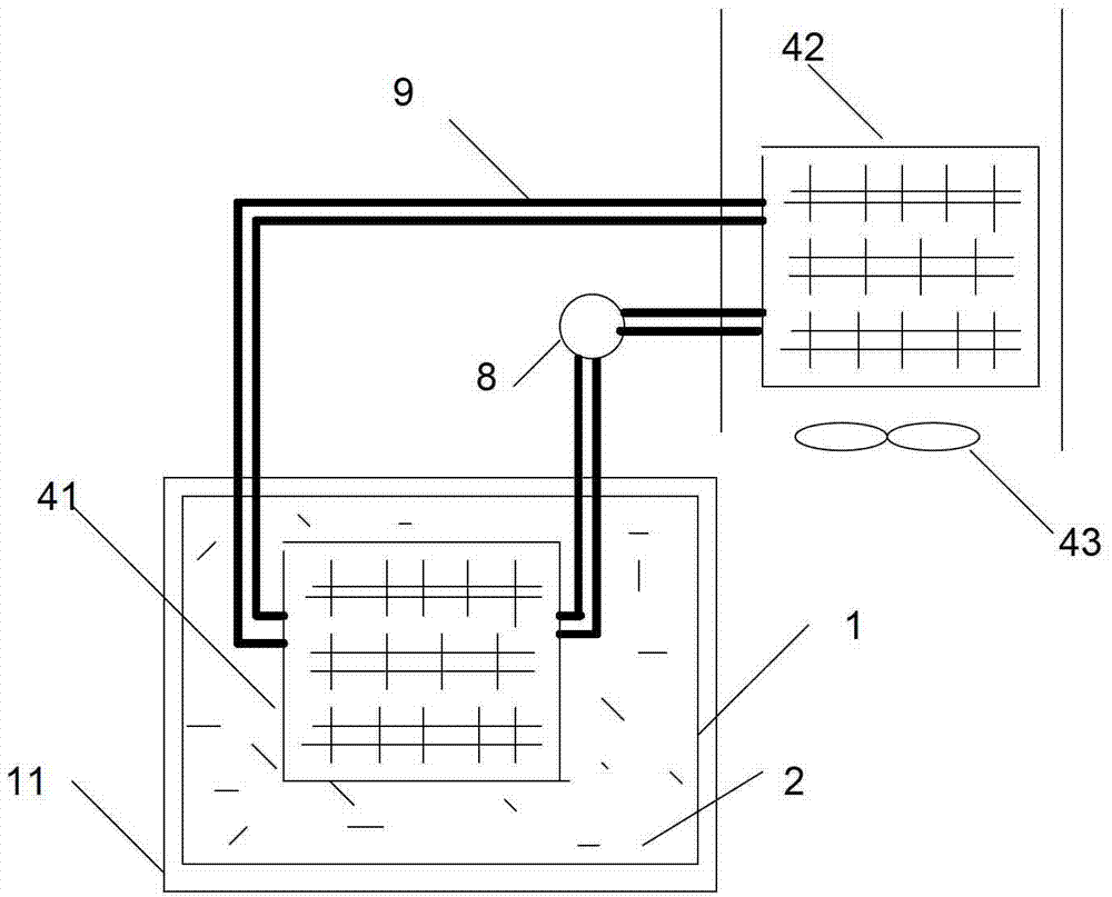
[0035] Different from Embodiment 1, the heat pump device of this embodiment adopts a closed-loop pump force circulation device. Such as image 3 As shown, the closed-loop pump force circulation device mainly includes a closed-loop path 9 (pipeline) with a heat transfer medium, and a circulation pump 8 in the closed-loop path. A part of the closed-loop path is set in the storage tank 1, and the other part is set in the waiting In the cooling (heating) area, the two parts are provided with radiators 41 and 42 respectively. In this embodiment, the radiator 42 is also provided with a cooling fan 43, which is generally more suitable for the occasions where fan coil units are used. In Embodiment 1, a cooling fan can also be added.
[0036] The control device of this embodiment is as Figure 4 As shown, its control device also takes power from the storage battery 6, and the controller controls the circulating pump 8 and the cooling fan 43. Regarding the way of using the air condi...
Embodiment 3
[0038] Such as Figure 5 As shown (the heat pump device is omitted in the figure, the heat pump device can adopt the heat pump device of Embodiment 1 or Embodiment 2), an electric heating device is added, and the electric heating device includes a control switch and an electric heater 21, and the electric heater 21 is installed in the box Between the body 1 and the insulation layer 11.
[0039] The outstanding feature of this embodiment is that the electric heating device is powered by another power source different from the heat pump device to generate heat. An implementation using a different power supply such as Figure 5, the electric heating device takes power from the DC part before the storage battery 6, and the heat pump device takes power from the DC part after the storage battery.
PUM
 Abstract
Description
Claims
Application Information
 - R&D
- Intellectual Property
- Life Sciences
- Materials
- Tech Scout
- Unparalleled Data Quality
- Higher Quality Content
- 60% Fewer Hallucinations
Browse by: Latest US Patents, China's latest patents, Technical Efficacy Thesaurus, Application Domain, Technology Topic, Popular Technical Reports.
© 2025 PatSnap. All rights reserved.Legal|Privacy policy|Modern Slavery Act Transparency Statement|Sitemap|About US| Contact US: help@patsnap.com


