Composite magnetic control sputtering cathode

A magnetron sputtering and composite technology, applied in the direction of discharge tubes, electrical components, circuits, etc., can solve the problem that the magnetic field cannot be adjusted flexibly, and achieve the effect of improving target utilization and wide application fields

Active Publication Date: 2014-07-30
INST OF ELECTRICAL ENG CHINESE ACAD OF SCI
View PDF5 Cites 1 Cited by
  • Summary
  • Abstract
  • Description
  • Claims
  • Application Information

AI Technical Summary

Problems solved by technology

[0006] The purpose of the present invention is to overcome the problem that the magnetic field cannot be adjusted flexibly during the use of conventional permanent magnet magnetron sputtering devices, and proposes a new permanent magnet electromagnetic composite magnetron sputtering cathode, which is different from existing electromagnetic and composite magnetron sputtering cathodes. The difference with the magnetron sputtering cathode is that the present invention can flexibly control the magnetic field intensity and distribution of a single magnetic pole independently

Method used


Image

  • Composite magnetic control sputtering cathode
  • Composite magnetic control sputtering cathode
  • Composite magnetic control sputtering cathode

Examples


Embodiment Construction

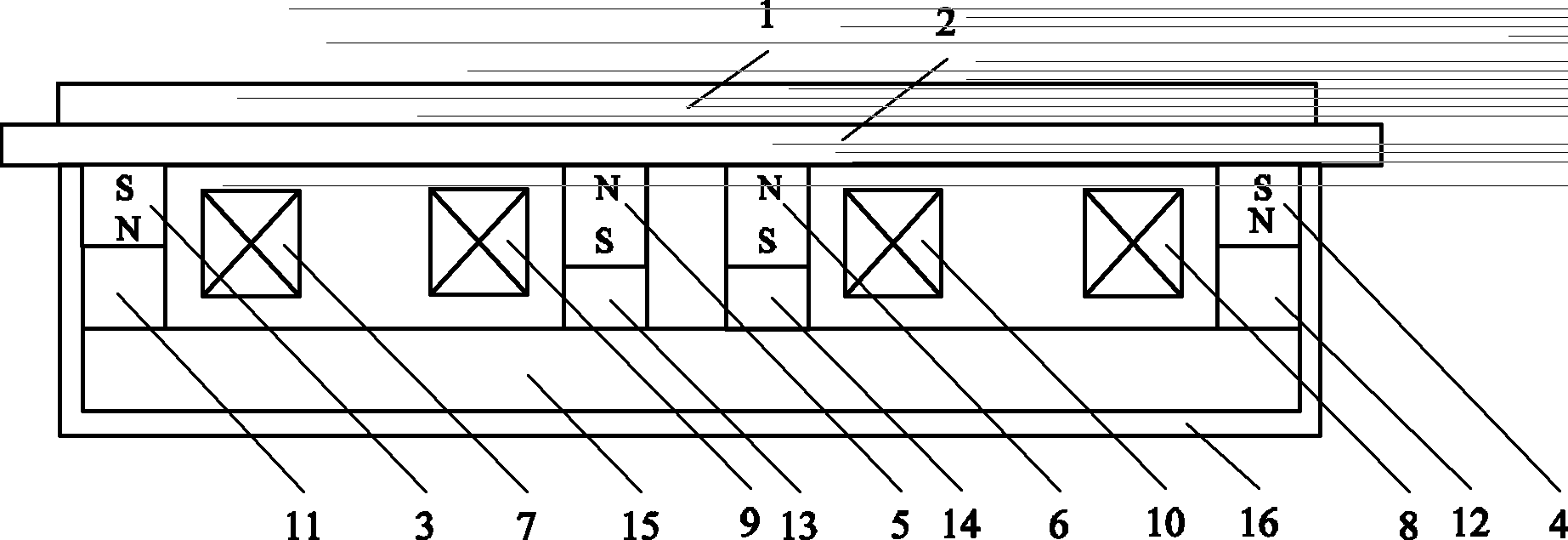
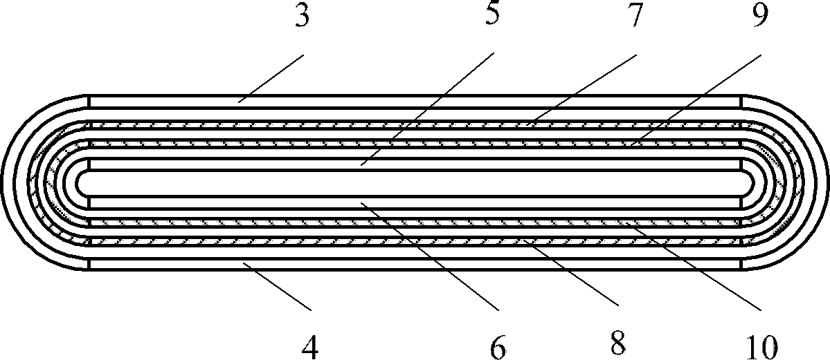
[0023] figure 1 It is a composite magnetron sputtering device of the present invention. Such as figure 1 As shown, the magnetron sputtering cathode is rectangular and flat, composed of a flat target material 1, a water-cooled back plate 2, outer permanent magnets 3 and 4, inner permanent magnets 5 and 6, outer electromagnetic coils 7 and 8, and inner Electromagnetic coils 9 and 10, outer yokes 11 and 12, inner yokes 13 and 14, bottom yoke 15 and frame 16. The water-cooled backplane 2 is a water-cooled frame structure containing cooling water, and a water-cooled pipe is left in the backplane. A plane target 1 is placed on the water-cooled backplane 2, and the plane target 1 and the water-cooled backplane 2 are closely installed together. Below the water-cooled back plate 2 is a magnet frame 16. The frame 16 contains outer permanent magnets 3 and 4, inner permanent magnets 5 and 6, outer electromagnetic coils 7 and 8, inner electromagnetic coils 9 and 10, outer yokes 11 and 12,...


PUM


Abstract

The invention relates to a composite magnetic control sputtering cathode, which consists of a plane target (1), a water cooling backboard (2), outer permanent magnets (3 and 4), inner permanent magnets (5 and 6), outer electromagnetic coils (7 and 8), inner electromagnetic coils (9 and 10), outer field yokes (11 and 12), inner field yokes (13 and 14), a bottom field yoke (15) and a framework (16). Polarity of each outer permanent magnet (3 and 4) is identical to each other, the polarity of each inner permanent magnet (5 and 6) is identical to each other, and the polarity of each outer permanent magnet is opposite to that of each inner permanent magnet. The two outer electromagnetic coils (7 and 8) form a closed coil, the two inner electromagnetic coils (9 and 10) form a closed coil, and the outer electromagnetic coils and the inner electromagnetic coils are respectively connected to a power supply through a lead wire. By adjusting the electrification current and the electrification current direction of the outer and the inner electromagnetic coils, the variation of the magnetic field strength and the magnetic field distribution shape of the magnetic control sputtering cathode can be realized, so the sputtering speed, the magnetic field balance and the target utilization rate can be adjusted.

Description

Technical field [0001] The invention relates to a magnetron sputtering equipment, in particular to a permanent magnet electromagnetic composite magnetron sputtering cathode. Background technique [0002] Magnetron sputtering is widely used in the field of material coating. The magnetron sputtering cathode target can be divided into planar magnetron sputtering target and cylindrical magnetron sputtering target from the structure, and divided into balanced target and unbalanced target from the magnetic field distribution. The target material used in the planar magnetron sputtering target is easy to process and manufacture, easy to install, and suitable for mass production of coated products. However, due to the low utilization rate of the planar target material, about 20%, especially when precious metals are plated on the substrate, Undoubtedly, the production cost is relatively high. With the mass production of low-emissivity films, the price of each set of silver targets used is...

Claims


Application Information

Patent Timeline
Patent Type & Authority Patents(China)
IPC IPC(8): H01J37/32
Inventor 邱清泉丁发柱戴少涛张志丰古宏伟
Owner INST OF ELECTRICAL ENG CHINESE ACAD OF SCI
Why Eureka
Try Eureka