Medical image diagnosis device and region-of-interest setting method therefor

A region of interest, medical image technology, applied in diagnosis, measurement device, acoustic diagnosis and other directions, can solve the problem of automatic setting of 3D image ROI without any enlightenment and so on

Active Publication Date: 2012-04-18
HITACHI HEALTHCARE MFG LTD
View PDF13 Cites 5 Cited by
  • Summary
  • Abstract
  • Description
  • Claims
  • Application Information

AI Technical Summary

Problems solved by technology

[0009] However, in Patent Document 1, the image to be processed is a two-dimensional ima

Method used


Image

  • Medical image diagnosis device and region-of-interest setting method therefor
  • Medical image diagnosis device and region-of-interest setting method therefor
  • Medical image diagnosis device and region-of-interest setting method therefor

Examples


Embodiment 1

[0030] In Embodiment 1, a case will be described in which a three-dimensional image including moving organs of a subject is acquired by an ultrasonic diagnostic apparatus, and a two-dimensional reference image is extracted from the acquired three-dimensional image by a CPU mounted in the ultrasonic diagnostic apparatus. , the ROI is automatically set based on the extracted two-dimensional reference image by the CPU mounted in the ultrasonic diagnostic apparatus.

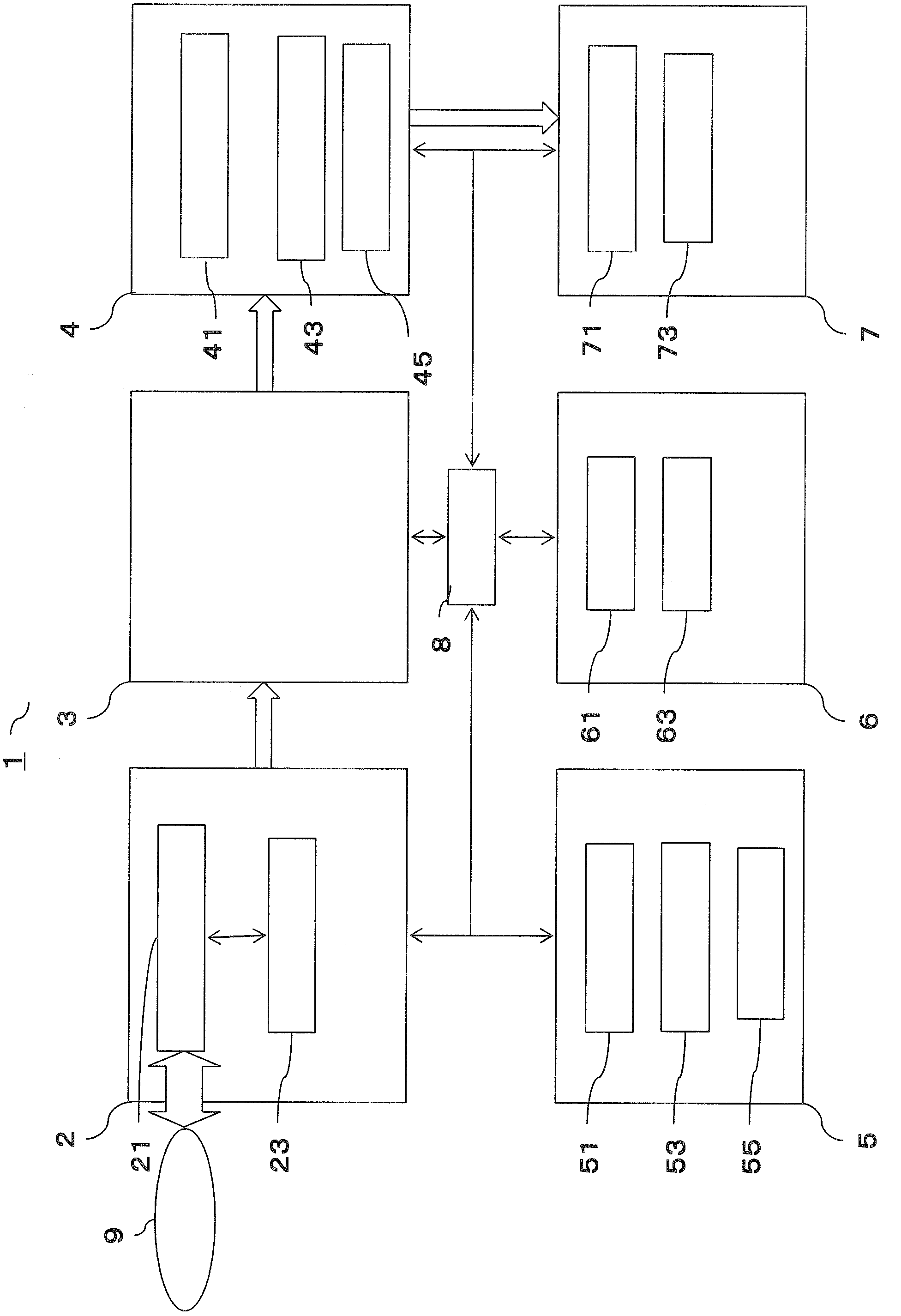
[0031] figure 1 is a schematic block diagram showing the ultrasonic diagnostic apparatus in this embodiment.

[0032] Such as figure 1 As shown, the ultrasonic diagnostic apparatus 1 includes an ultrasonic signal generation unit 2 , an ultrasonic image generation unit 3 , a calculation unit 4 , a storage unit 5 , a setting unit 6 , a display unit 7 , and a control unit 8 . The solid arrows in the figure indicate control, and the white arrows indicate the flow of image signal data.

[0033] The ultrasonic signal ge...

Embodiment 2

[0109] In Embodiment 2, a case will be described in which the model stored in the database unit 53 is not referred to.

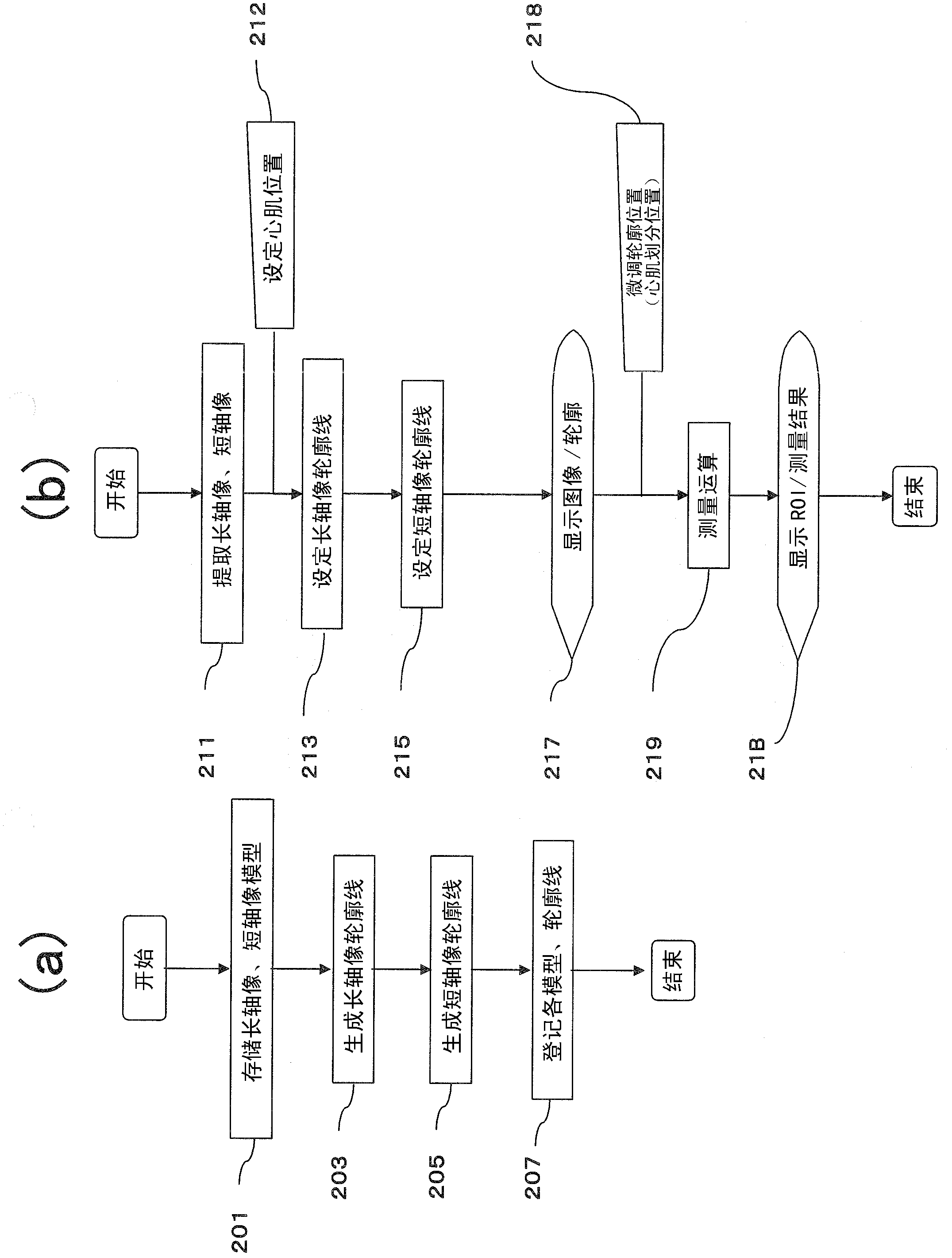
[0110] Figure 5 It is a flowchart of the measurement processing of the ultrasonic diagnostic imaging apparatus according to the second embodiment of the present invention. Figure 6 yes means Figure 5 A diagram of an example of the setting of the contour line.

[0111] (step 511)

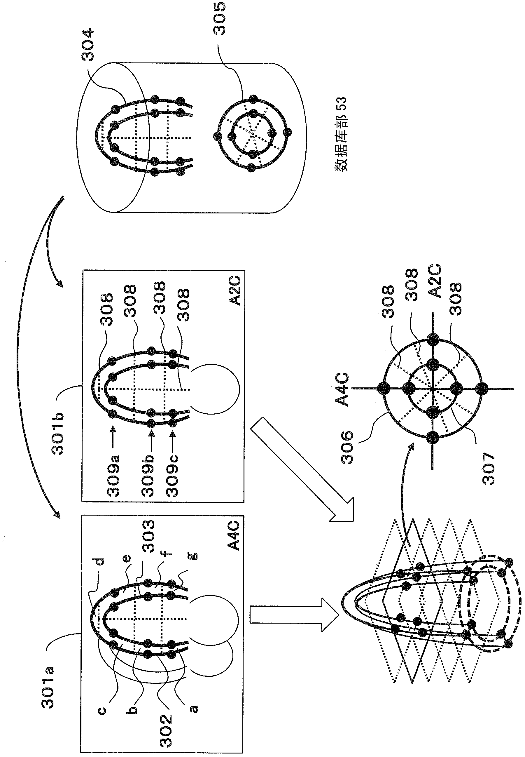
[0112] The control unit 8 extracts long-axis images (the A2C image and the A4C image) from the three-dimensional ultrasonic signal by known image recognition. The control unit 8 causes the display unit 7 to display the extracted long-axis image. The examiner uses the measurement condition setting unit 61 to manually set the endocardial and endocardial contours on the A2C image and the A4C image for the long-axis image displayed on the display unit 7 . Furthermore, the examiner uses the measurement condition setting unit 61 to set the division boundary of the myocardial divisi...

Embodiment 3

[0120] In Example 1, the case where the long-axis image or the short-axis image is perpendicular to each other was described.

[0121] However, the positional relationship between the long-axis image and the short-axis image does not have to be orthogonal, and if the angle has a specific relationship, it is not limited to orthogonal or non-orthogonal, and the type of reference cross-section can be freely determined. Because the difference between Embodiment 1 and Embodiment 3 lies in the orthogonal or non-orthogonal positional relationship, only the difference in positional relationship will be described here.

[0122] Figure 7 It is an example of the setting of the outline which shows Example 3 of this invention.

[0123] For example, if Figure 7 As shown in the lower left, the three-dimensional contour surface is truncated by the long-axis section obliquely intersecting with AC4, and then becomes Figure 7 Slanted axes shown below right. If the relative position of the...


PUM


Abstract

A medical image diagnosis device is provided with a medical image acquiring unit for acquiring a medical image, a three-dimensional image constructing unit for constructing a three-dimensional image including a moving organ region in the medical image, a tomogram creating unit for creating a two-dimensional tomogram to serve as a reference image from the three-dimensional image, a region dividing unit for dividing the reference image into a plurality of regions according to the criteria for region division, and a region-of-interest setting unit for computing the moving states of the regions, specifying at least one region from among the regions according to the computed moving states, and setting a region in the medical image including the specified region as a region of interest.

Description

technical field [0001] The present invention relates to a medical image diagnostic apparatus capable of improving operability in setting a region of interest (ROI) in a medical image and a method for setting a region of interest therefor. Background technique [0002] Medical imaging diagnostic devices are used by examiners such as doctors and clinical laboratory technicians. When the examiner uses the medical image diagnosis apparatus, an ROI is set for a part of the diagnosis region of the image. [0003] The examiner sets the ROI by tracing a part of the image displayed on the display screen using the pointing device. The tracking operation performed by the examiner's hand is called ROI manual setting. When it is necessary to set ROIs for each of a plurality of images acquired by the medical imaging diagnostic apparatus, manual setting of ROIs is complicated for the examiner. [0004] On the other hand, it is known that among ROIs set for moving organs such as the hear...

Claims


Application Information

Patent Timeline
IPC IPC(8): A61B8/08
CPCA61B8/00A61B8/466G01S7/52063A61B8/0883A61B8/52G01S15/8993A61B8/483A61B8/469G01S7/52066
Inventor 长野智章
Owner HITACHI HEALTHCARE MFG LTD
Why Eureka
Try Eureka