Ultrasonic diagnostic apparatus and method of displaying ultrasonic image
a diagnostic apparatus and ultrasonic technology, applied in the field of ultrasonic diagnostic equipment, to achieve the effect of easy recognition of the area
- Summary
- Abstract
- Description
- Claims
- Application Information
AI Technical Summary
Benefits of technology
Problems solved by technology
Method used
Image
Examples
embodiment 1
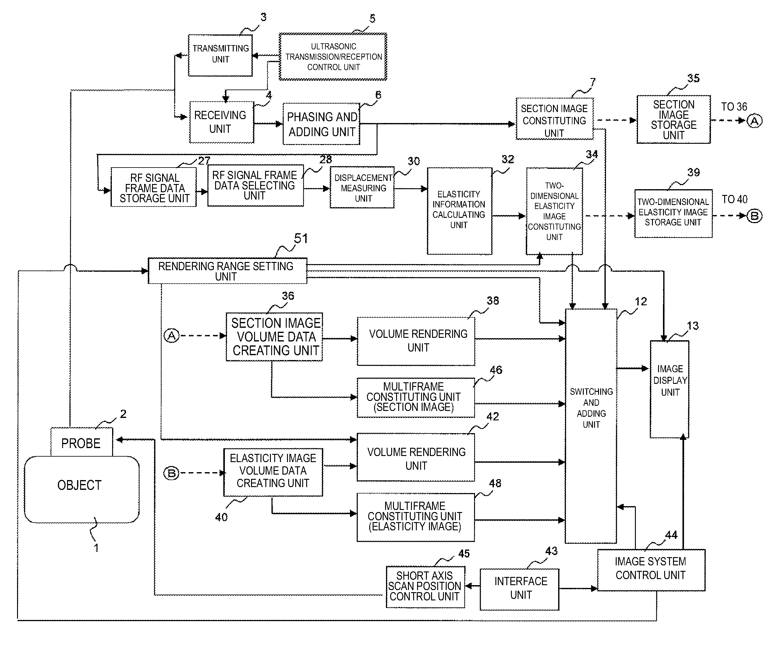
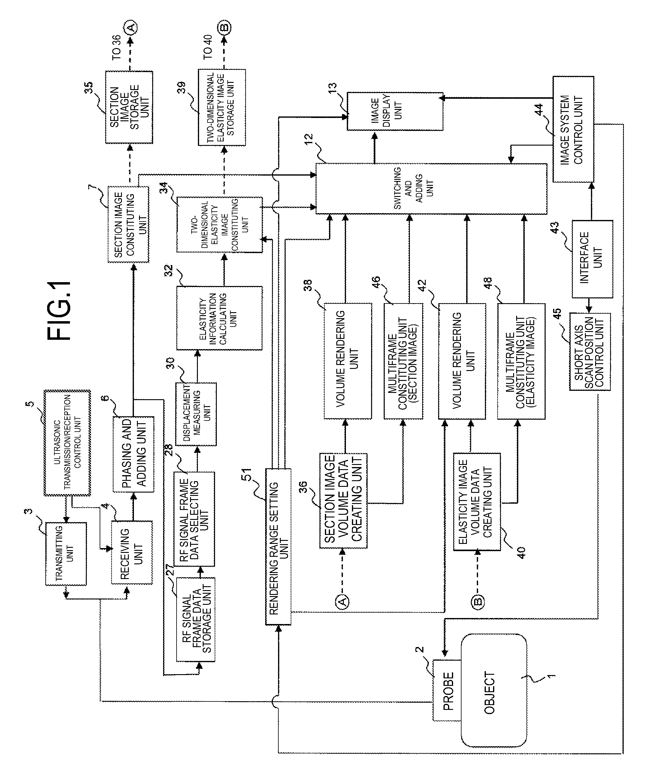
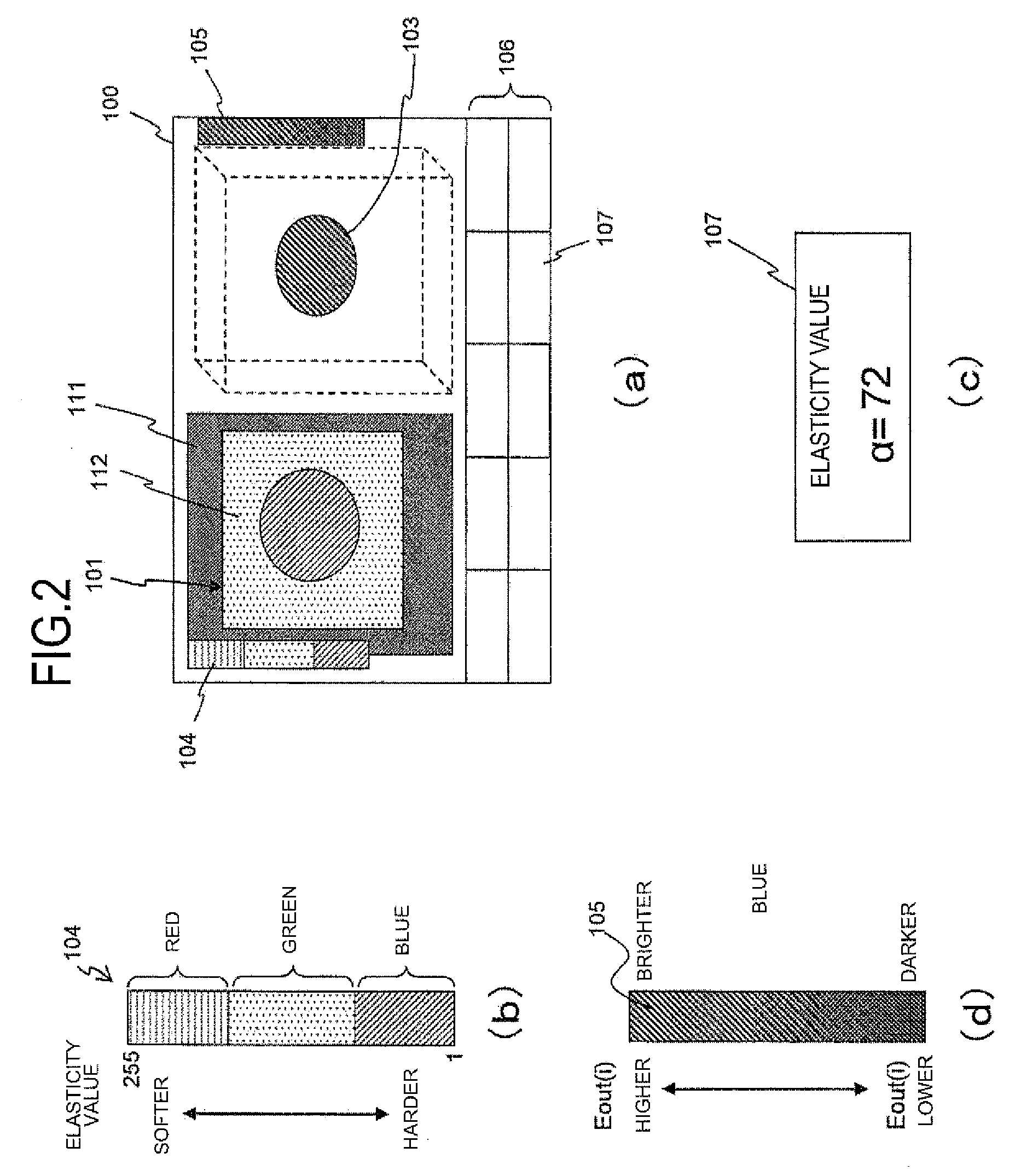
[0078]The ultrasonic diagnostic apparatus of Embodiment 1 includes the section image constituting unit 7 which produces the section image of the object using the received signal as a result of the ultrasonic transmitted into the object, the two-dimensional elasticity image constituting unit 34 which processes the signal to produce the two-dimensional elasticity image for the elasticity value representing the elasticity, the rendering unit 42 which produces the volume data formed of the plurality two-dimensional elasticity images, and selects and renders the elasticity value data of the volume data included in the desired elasticity value range to produce the three-dimensional elasticity image for the elasticity value data within the elasticity value range, and the display unit 13 which displays the three-dimensional elasticity image and at least one of the two-dimensional elasticity image and the section image showing the area associated with the elasticity value range. In the metho...
embodiment 2
[0100]In Embodiment 2, the area outside the elasticity value range set as the rendering range is transparently displayed in the two-dimensional elasticity image of the combined image displayed in the left area on the screen 100 as shown in FIG. 7.
[0101]Specifically, the following expressions (21) to (26) are used in putting the weight on the two-dimensional elasticity image with the mask M1(x,y) at steps 62 and 64 of FIG. 5 in Embodiment 1.
[0102]When M1(x,y)=1, then
D(R)(x,y)=E(R)(x,y)×r+C(R)(x,y) expression (21)
D(G)(x,y)=E(G)(x,y)×r+C(G)(x,y) expression (22)
D(B)(x,y)=E(B)(x,y)×r+C(B)(x,y) expression (23)
[0103]when M1(x,y)=0, then
D(R)(x,y)=C(R)(x,y) expression (24)
D(G)(x,y)=C(G)(x,y) expression (25)
D(B)(x,y)=C(B)(x,y) expression (26)
[0104]As apparent from the expressions (24) to (26), the two-dimensional elasticity image 112 is not combined in the area (the area of M1(x,y)=0) outside the elasticity value range set as the rendering range, so that the two-dimensional elasticity i...
embodiment 3
[0106]In Embodiment 3, at steps 62 and 65 of FIG. 5 in Embodiment 1, the combined image is produced by filling in the area of the elasticity value range set as the rendering range with a predetermined single color corresponding to the elasticity value of that area.
[0107]Specifically, the following expressions (27) to (32) are used in putting the weight on the two-dimensional elasticity image with the mask M1(x,y) 110 as shown in FIG. 8(a) at steps 62 and 64 in Embodiment 1.
[0108]When M1(x,y)=1, then
D(R)(x,y)=K(R)(x,y) expression (27)
D(G)(x,y)=K(G)(x,y) expression (28)
D(B)(x,y)=K(B)(x,y) expression (29)
[0109]When M1(x,y)=0, then
D(R)(x,y)=E(R)(x,y)×r×w+C(R)(x,y) expression (30)
D(G)(x,y)=E(G)(x,y)×r×w+C(G)(x,y) expression (31)
D(B)(x,y)=E(B)(x,y)×r×w+C(B)(x,y) expression (32)
[0110]K(R), K(G), and K(B) represent hues predefined in accordance with the elasticity values of the elasticity value range (M1(x,y)=1) set as the rendering range. For example, when the elasticity value range ...
PUM
 Abstract
Description
Claims
Application Information
 - R&D
- Intellectual Property
- Life Sciences
- Materials
- Tech Scout
- Unparalleled Data Quality
- Higher Quality Content
- 60% Fewer Hallucinations
Browse by: Latest US Patents, China's latest patents, Technical Efficacy Thesaurus, Application Domain, Technology Topic, Popular Technical Reports.
© 2025 PatSnap. All rights reserved.Legal|Privacy policy|Modern Slavery Act Transparency Statement|Sitemap|About US| Contact US: help@patsnap.com


