
Blade mounting

A rotor blade, on-site installation technology, applied in the installation/support of wind turbine configuration, wind turbine assembly, engine function, etc., can solve the problems of bulkiness, instability and time-consuming, and achieve low investment cost and cost-effective Effect

Inactive Publication Date: 2012-04-18
GE WIND ENERGY NORWAY
View PDF8 Cites 13 Cited by
  • Summary
  • Abstract
  • Description
  • Claims
  • Application Information

AI Technical Summary

Problems solved by technology

This is a bulky, unstable and time-consuming solution

Method used


Image

  • Blade mounting
  • Blade mounting
  • Blade mounting

Examples


Embodiment Construction

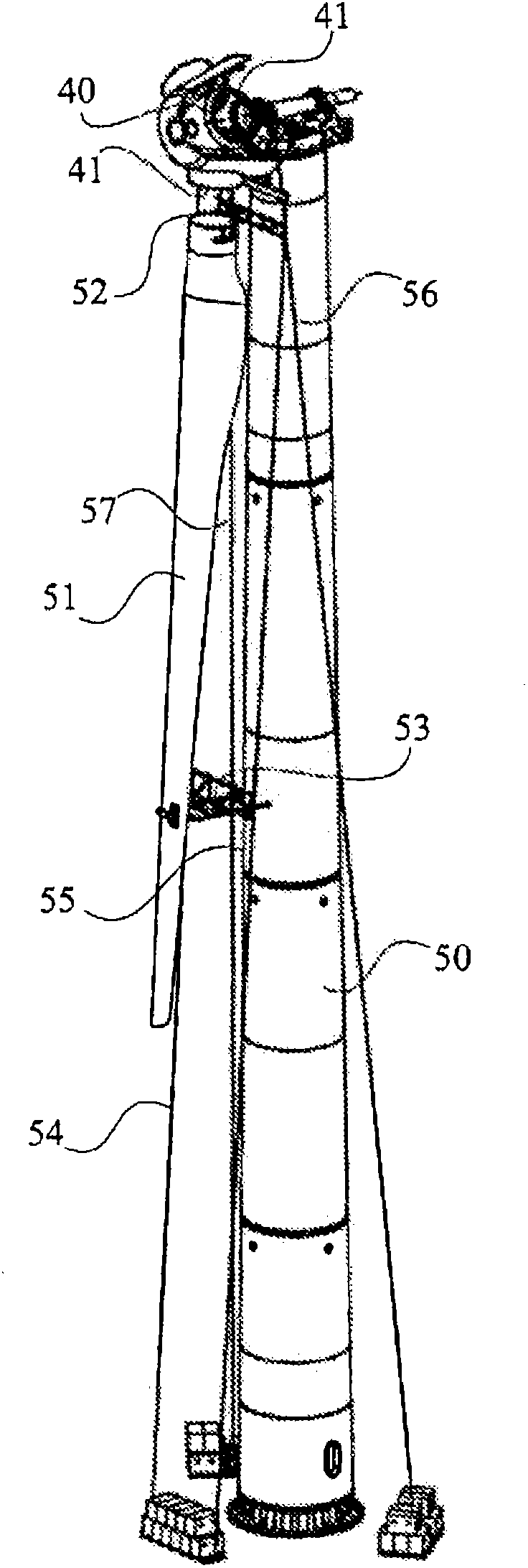
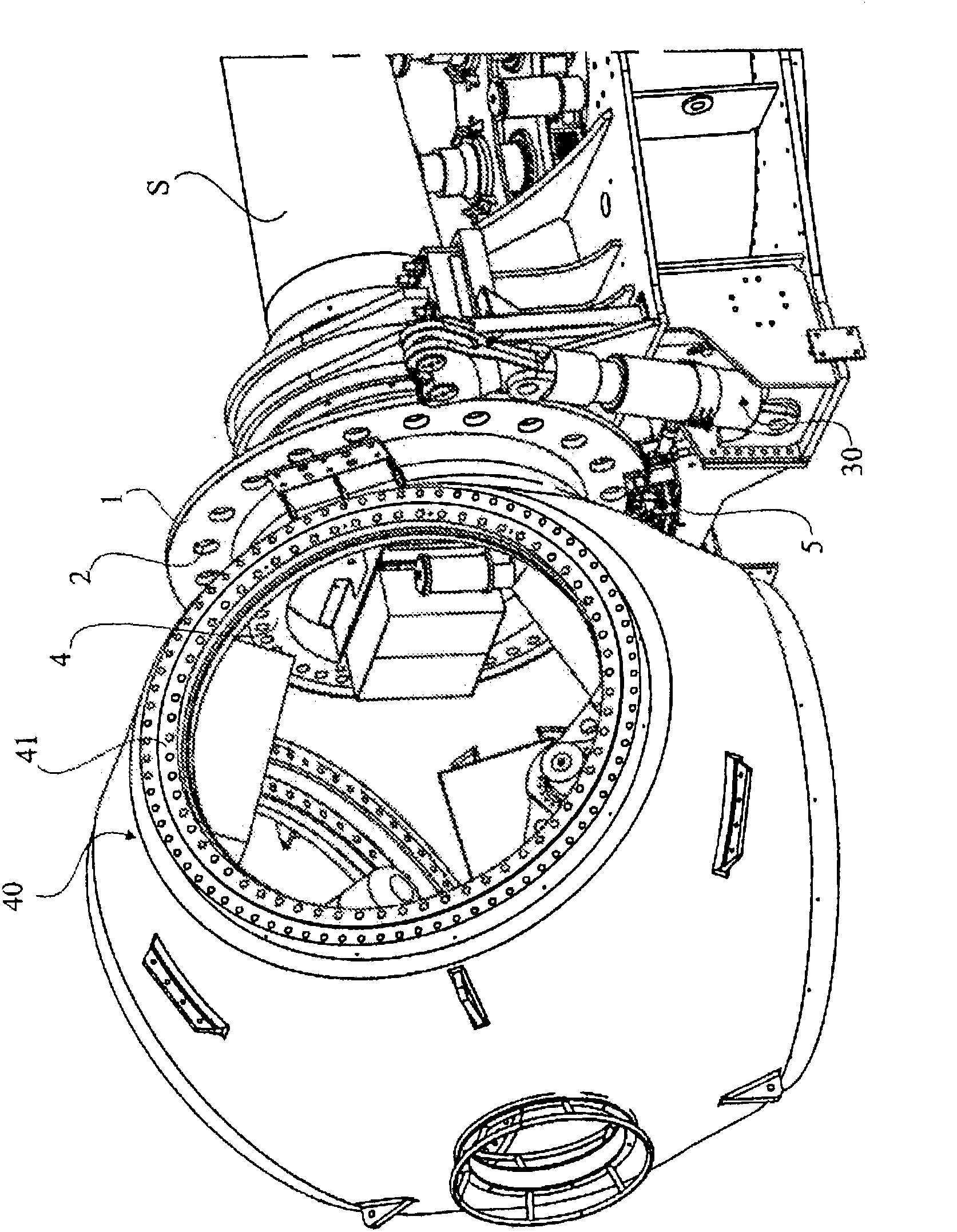
[0022] figure 1 An overview map of wind power equipment. The rotor blade 51 is lifted to the rotor hub 40 at the upper part of the tower 50 so as to be fitted with its rotor blade connection 52 onto the flange 41 of the rotor hub 40 through which the rotor hub 40 passes through the hub flange (in figure 2 shown in ) to the spindle.

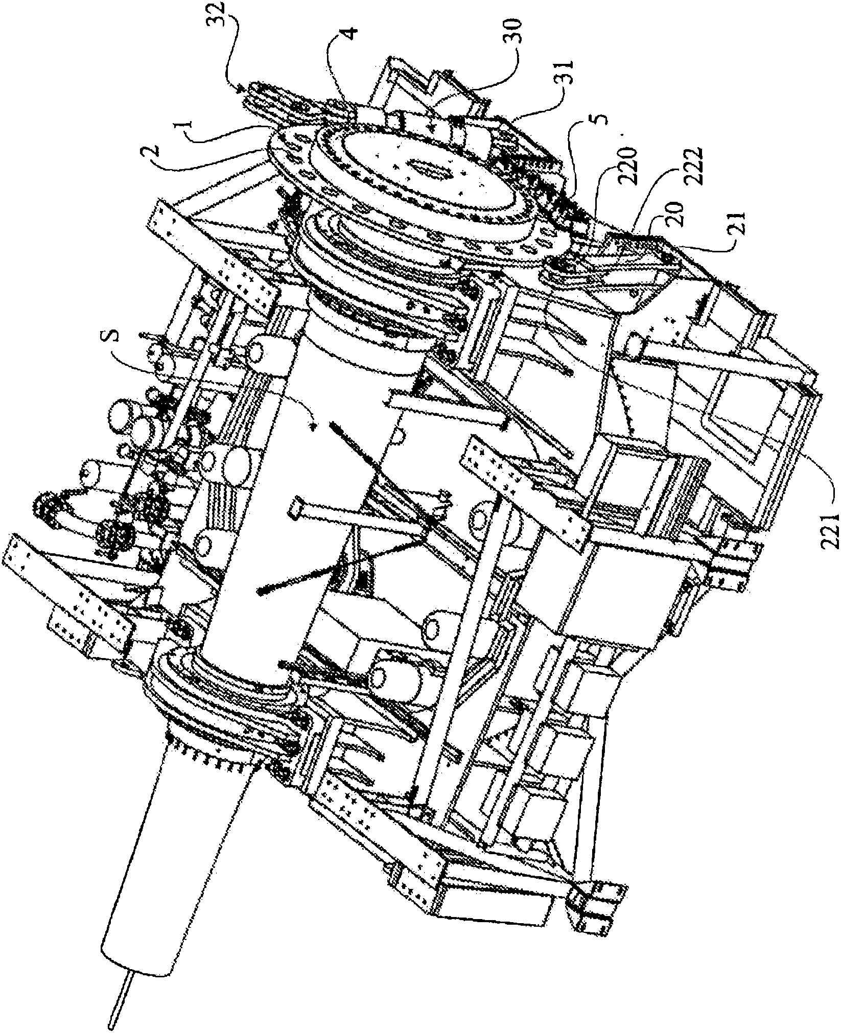
[0023] figure 2 It is a side view of the inside of the machine housing of the wind power plant. The brake disc 1 is mounted centrally to the main shaft S of the wind turbine and has a relatively large diameter generally in the range of 1.5 to 3 metres. The brake disc 1 extends such that part of its circumference enters the gaps of a number of brake units 5 . The brake disc 1 is provided with connection means 2 consisting of a number of through holes distributed evenly over the brake disc 1 at a certain distance from the axis of the brake disc 1 . The number of vias and the angle between vias can vary depending on different requirements. Th...


PUM


Abstract

The present invention concerns an arrangement for in situ mounting of rotor blades to a rotor hub of a wind power plant comprising rotor blades, a rotor hub (40), a disc (1), a means for rotation (30) of the disc (1) around its axis. The disc (1) is in connection with the rotor hub (40) in such a way that when the disc (1) rotates a certain degree of angle around its axis (3) it will cause the rotor hub (40) to rotate the same degree of angle around the axis of the rotor hub. When the means for rotation (30) comes into a desired position, the disc (1) is secured by a securing means (20; 36, 37).

Description

technical field [0001] The present invention relates to the field of wind power plant construction, and more particularly to an arrangement and a method for on-site mounting of rotor blades to a rotor hub of a wind power plant. [0002] Various aspects of the invention also relate to a wind power installation implementing the method. Background technique [0003] The most common way for mounting the rotor blades to the rotor hub is to perform the mounting on the ground, ie all the rotor blades fit onto the flanges of the rotor hub, which rests on the ground. When all the rotor blades are fitted and in place, the rotor hub with the installed rotor blades is lifted onto the top of the tower. Lifting of a rotor hub with several rotor blades mounted to the hub is a difficult and dangerous operation because of the high total weight of the rotor hub and the rotor blades together. Lifting is weather dependent and usually only possible on calm days with no wind. The geographical ...

Claims


Application Information

Patent Timeline
Patent Type & Authority Applications(China)
IPC IPC(8): F03D1/06F03D7/02F03D11/00
CPCY02E10/723F05B2260/30Y02E10/722Y02E10/72F03D11/00F03D1/003F03D1/0658F03D7/0268Y02E10/728F03D1/001Y02E10/721F03D80/00F03D13/10F03D80/50Y10T29/37F05B2260/31F03D13/108F03D1/066
Inventor M·林德贝里J·赫德贝里
Owner GE WIND ENERGY NORWAY
Learn More