AI technical title is built by Patsnap AI team. It summarizes the technical point description of the patent document.
A retarder brake, coaxial technology, applied in the direction of hydraulic brake transmission, brake transmission, control device, etc., can solve the problem of heavy-duty vehicles with retarders, etc., to achieve light weight, convenient installation and Modification, soft braking effect
Inactive Publication Date: 2013-07-31
谢陵波
View PDF9 Cites 0 Cited by
Summary
Abstract
Description
Claims
Application Information
AI Technical Summary
This helps you quickly interpret patents by identifying the three key elements:
Problems solved by technology
Method used
Benefits of technology
Problems solved by technology
In the case of brake heat fading, even a well-regulated driver cannot stop the car within the ideal distance, so it is very urgent to configure a retarder for heavy vehicles
Method used
Image
Click on the blue label to locate the original text in one second.
Reading with bidirectional positioning of images and text.
Examples
Embodiment Construction
[0017] The present invention will be described in further detail below in conjunction with the accompanying drawings and specific embodiments.
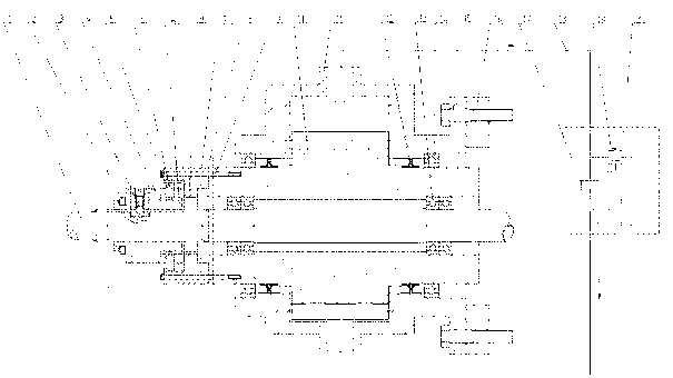
[0018] Such as figure 1 As shown, a coaxial hydraulic retarding brake device includes a transmission shaft 1 , a shift fork 2 , a positioning mechanism 3 , a clutch assembly 8 , an oil pump rotor 10 , an oil pump housing 11 and an oil pressure control system 20 .
[0019] Wherein, the oil pump rotor 10 is a hollow rotating shaft, and bearings 13 are respectively installed in both ends of the inner hole of the oil pump rotor 10, and the oil pump rotor 10 is sleeved on the transmission shaft 1 through the bearings 13 and is axially fixed with the transmission shaft 1 and can rotate radially Cooperate. Bearings 14 are installed at both ends of the outer circle of the oil pump rotor 10, and the oil pump housing 11 is sleeved on the oil pump rotor 10 through the shaft sleeve 14 and is axially fixed and radially rotatable with the oil ...
PUM
Abstract
The invention discloses a coaxial type hydraulic retarding braking device, which comprises a transmission shaft, a pulling fork, a positioning mechanism, a clutch assembly, an oil pump rotor, an oil pump casing and an oil pressure control system, wherein the oil pump rotor is born on the transmission shaft through a bearing, a clutch inner sleeve is born on the transmission shaft through a sliding spline in a matching way, a clutch outer sleeve is fixedly connected onto the oil pump rotor for realizing the clutching of the transmission shaft and the rotor, and the oil pump casing is connectedonto a machine frame through screw bolts. The coaxial type hydraulic retarding braking device has the advantages that the size is compact, the weight is light, the energy is saved, the reliability isrealized, and the service life is long. The braking device is convenient to install and refit, the braking force is not attenuated after long-time work, no power consumption is generated during no work, the safety factor is improved, the braking is mild and smooth, no collision is caused, and the coaxial type hydraulic retarding braking device is suitable for vehicle braking, is also suitable forhydraulic motor driving and can also be used for deep wells, deep seas, tool and substance hanging and conveying and the like.
Description
technical field [0001] The invention relates to a hydraulic retarder, in particular to a coaxial hydraulic retarder. Background technique [0002] With the rapid development of my country's economy and the improvement of road infrastructure conditions, the speed of vehicles is getting faster and faster, and there are more and more heavy vehicles. The number of accidents is on the rise year by year. [0003] On May 4, 2009, a major accident occurred in Yunnan Province of my country due to a truck brake failure. Three vehicles collided and one vehicle lost control and drove off the road, killing 14 people and injuring 50 others. The cause of the accident investigation: The truck driven by the perpetrator braked continuously on a 6-kilometer downhill road, which increased the wear time of the brake shoes and brake drum, resulting in an increase in the temperature of the brake drum, resulting in thermal decay, and eventually led to brake failure. In the past two years, the numb...
Claims
Application Information
Patent Timeline
Application Date:The date an application was filed.
Publication Date:The date a patent or application was officially published.
First Publication Date:The earliest publication date of a patent with the same application number.
Issue Date:Publication date of the patent grant document.
PCT Entry Date:The Entry date of PCT National Phase.
Estimated Expiry Date:The statutory expiry date of a patent right according to the Patent Law, and it is the longest term of protection that the patent right can achieve without the termination of the patent right due to other reasons(Term extension factor has been taken into account ).
Invalid Date:Actual expiry date is based on effective date or publication date of legal transaction data of invalid patent.

