
Method for mounting large-area refractory fiber module

A fiber module and refractory fiber technology, applied in the direction of the overall lining, etc., can solve the problems of easy sagging, uneven laying, and difficult observation of the tiled carpet, and achieve the effect of easy and fast installation, easy promotion, and good appearance quality.

Active Publication Date: 2012-04-25
CHINA FIRST METALLURGICAL GROUP
View PDF3 Cites 11 Cited by
  • Summary
  • Abstract
  • Description
  • Claims
  • Application Information

AI Technical Summary

Problems solved by technology

[0004] (2) Due to the many solder joints of the anchor bolts and the wide operation area, it is easy to cause a large deviation during the marking and positioning process, and it is not vertical, which makes the installation of the fiber module inconvenient or even impossible.
[0005] (3) When laying flat fiber blankets, especially when laying the top, due to the gravity of the earth, the flat blankets are easy to sag, resulting in uneven laying, and the fiber module and the furnace shell steel plate cannot be tightly combined
[0006] (4) When installing a single fiber module, due to the large size of the module itself and the small diameter of the built-in PVC guide cylinder, it is difficult to observe and determine whether to align the module with the anchor bolt and push it in, and the installation efficiency is low
[0007] (5) Since the fiber module has been compressed and bundled into shape, the binding belt and the plywood on both sides need to be removed during the on-site installation process, which will easily cause the inside of the fiber module to become loose, and there will be gaps between the fiber module blocks and between rows. Reduced, affecting the life of the heating furnace

Method used


Image

  • Method for mounting large-area refractory fiber module
  • Method for mounting large-area refractory fiber module
  • Method for mounting large-area refractory fiber module

Examples


Embodiment Construction

[0062] In order to better understand the present invention, the technical solutions of the present invention will be further described below in conjunction with the embodiments and the accompanying drawings.

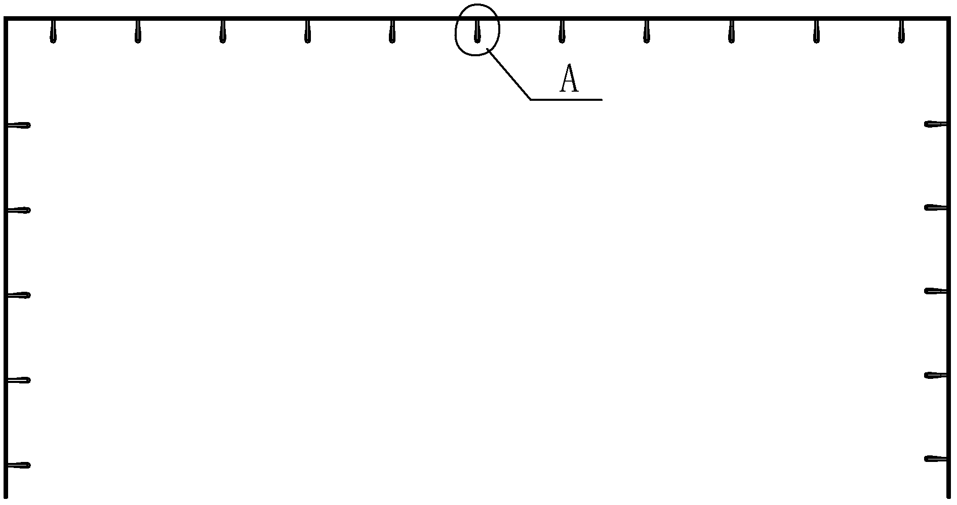
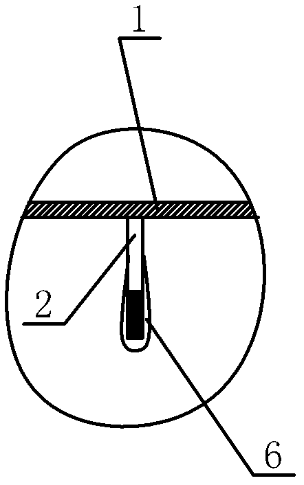
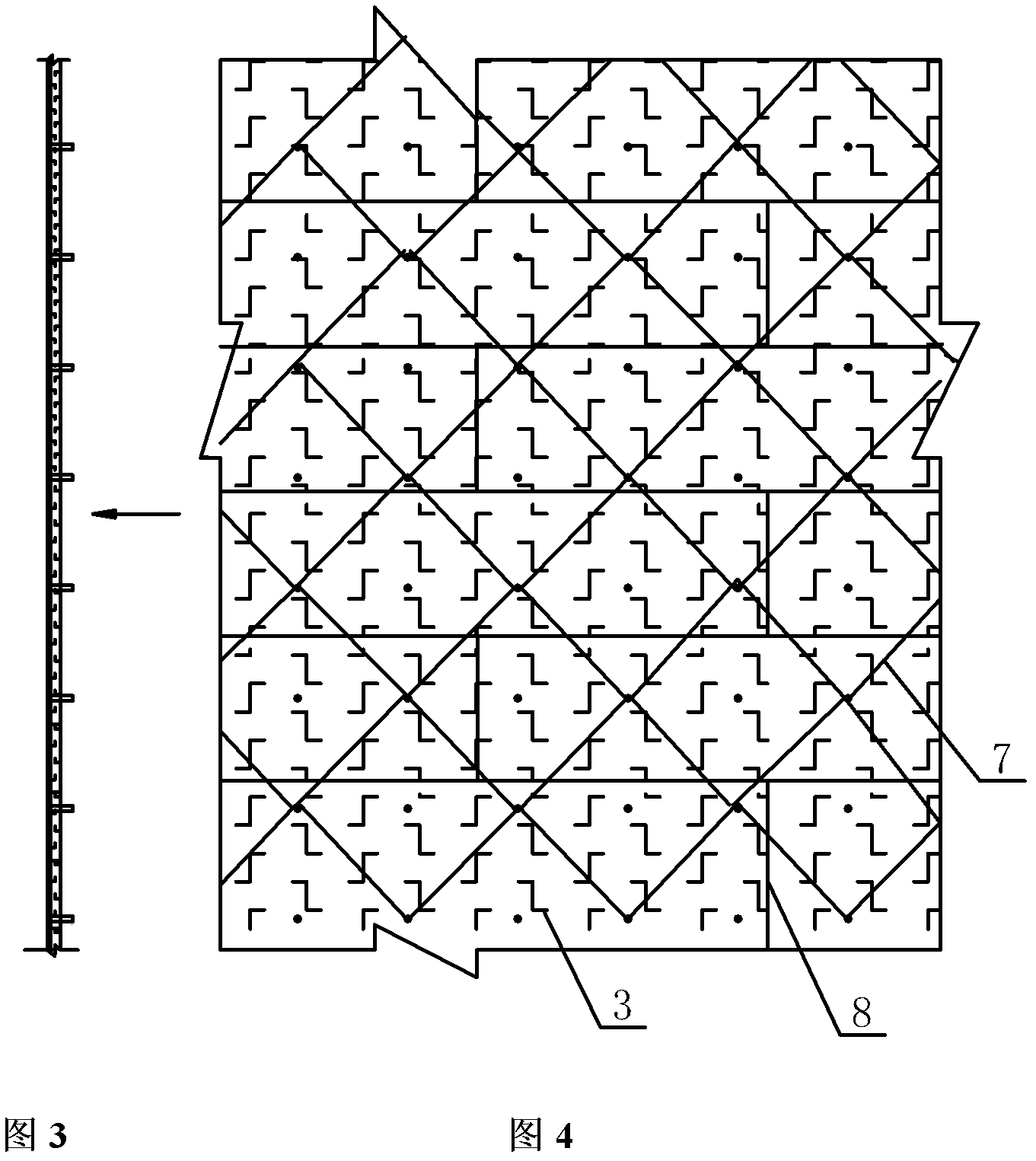
[0063] The large-area refractory fiber module installation method provided by the present invention is to adopt a fiber module installation device mainly composed of a metal guide cylinder 10, a fiber module installation wrench 11, a module installation guide plate 13, a pressure plate 14, and a U-shaped pin 15. For the method of installing fiber modules, see Figure 1 to Figure 15 , the method is:

[0064] The first step of construction preparation: the preparation of necessary auxiliary tools should include metal guide cylinder 10, fiber module installation wrench 11, module installation guide plate 13, pressure plate 14, U-shaped pin 15, and the steel plate of the shell 1 has rust, paint and Oil stains should be dealt with.

[0065] The second step is to measure the...


PUM


Abstract

The invention provides a method for mounting a large-area refractory fiber module, which relates to a method for mounting the large-area refractory fiber module by using a fiber module mounting device which mainly comprises a metal guiding barrel (10), a fiber module mounting wrench (11), a module mounting guide plate (13), a pressing plate (14) and a U-shaped contact pin (15). The method comprises the following steps of: performing construction preparation; measuring, and ruling; welding and anchoring a bolt (2); spreading a tiled blanket (3); mounting a fiber module (4); filling a compensation blanket (5); and checking and dressing. In the method, the metal guide pipe is used, so that quick positioning can be realized; the fiber module mounting wrench is used, so that the problem that a common wrench cannot be stretched into a polyvinyl chloride (PVC) guiding barrel to align a nut with a screw rod fastening bolt due to a thicker fiber module and a shorter anchoring bolt is solved; the module mounting guide plate is used, so that the last fiber module in each row can be easily and quickly mounted; the invention has the characteristics that: the method is economic and practical; and the invention has the advantages that: the method is easy to popularize, and the like.

Description

technical field [0001] The invention relates to the technical field of fiber module installation, in particular to a method for installing a large-area refractory fiber module in the inner lining of a heating furnace. Background technique [0002] In the selection of materials for the inner lining of the heating furnace in the past, castables and plastics were mostly used, and a large-area integral casting was formed on-site with a template. With the continuous innovation of heating furnace technology and refractory materials, in recent years, refractory fiber modules are mostly used in the lining of heating furnaces, and are used in large areas. A layer of refractory fiber tiled blanket is laid on the furnace shell first, and the working layer is refractory fiber modules. Compensation blankets are placed between every two rows of modules, and the fiber modules are fixed to the steel plate of the furnace shell through anchor bolts. The following problems are prone to occur d...

Claims


Application Information

Patent Timeline
IPC IPC(8): F27D1/10
Inventor 李胜涛鲍黎明黎耀南王青春李国庆
Owner CHINA FIRST METALLURGICAL GROUP
Learn More