Hartmann wavefront sensor with adjustable dynamic range

A dynamic range and sensor technology, applied in the field of new optical dynamic wavefront sensors, can solve the problems of large dynamic range and high measurement accuracy, and achieve the effect of ensuring measurement accuracy, reducing requirements and reducing impact

Active Publication Date: 2012-04-25
INST OF OPTICS & ELECTRONICS - CHINESE ACAD OF SCI
View PDF5 Cites 15 Cited by
  • Summary
  • Abstract
  • Description
  • Claims
  • Application Information

AI Technical Summary

Problems solved by technology

[0004] The technical problem of the present invention is: to overcome the problem that the Hartmann wavefront sensor has a large dynamic range and high measurement accuracy and it is difficult to balance it, and proposes an adjustable d

Method used


Image

  • Hartmann wavefront sensor with adjustable dynamic range
  • Hartmann wavefront sensor with adjustable dynamic range
  • Hartmann wavefront sensor with adjustable dynamic range

Examples


Embodiment 1

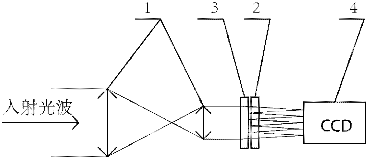
[0018] Such as figure 1 As shown, the component for compensating the wavefront aberration in the sub-aperture adopts the transmissive phase modulator 3, which is located before the wavefront division sampling array 2, and compensates the oblique aberration of the sub-wavefront in each sub-aperture. It includes an optical matching system 1, a wavefront division sampling array 2, transmissive phase modulator 3 and photoelectric sensor 4, the incident light wave is narrowed by the optical matching system 1, and passes through the transmissive phase modulator 3 before entering the wavefront split sampling array 2, the transmissive phase modulator can adjust the light wave Adding specific aberrations, the sub-apertures of the wavefront split sampling array 2 divide the light wave into many sub-beams, the focal plane of which coincides with the target surface of the photoelectric sensor 4, and the sub-beams in each sub-aperture are respectively focused on the target surface of the ph...

Embodiment 2

[0037] Such as Figure 4 As shown, the wavefront aberration compensation element in the sub-aperture adopts a transmissive phase modulator 3, which is located before the wavefront division sampling array 2 before the optical matching system, and compensates the wavefront aberration in each sub-aperture, which includes an optical matching system 1, a wavefront The front split sampling array 2, the transmissive phase modulator 3 and the photoelectric sensor 4, the incident light wave enters the wave front split sampling array 2 after being narrowed by the optical matching system 1, and the sub-aperture of the wave front split sampling array 2 splits the light wave into many sub-apertures The focal plane of the light beam coincides with the target surface of the photoelectric sensor 4, and the sub-beams in each sub-aperture are respectively focused on the target surface of the photoelectric sensor 4. The transmissive phase modulator is placed before the optical matching system, an...


PUM


Abstract

The invention provides a Hartmann wavefront sensor with an adjustable dynamic range, which consists of an optical matching system, a wavefront division sampling array, a phase modulator and a photoelectric sensor, wherein the optical matching system is used for shrinking an incident light wave so that the size of the incident light wave is less than the size of the wavefront division sampling array and the size of the phase modulator; the phase modulator is arranged between the optical matching system and the wavefront division sampling array, and the caliber of the phase modulator is greaterthan the clear caliber of the optical matching system; the phase modulator adds aberration to the shrunk incident wave, and multiple subareas are formed in the clear caliber of the phase modulator; the subareas and the sub-apertures of the wavefront division sampling array are in one-to-one correspondence in caliber and distribution, and the generated aberration is added to the light wave passingthrough the corresponding sub-aperture; and the wavefront divisions sampling array divides the light wave processed by the phase modulator into multiple sub-beams, and focuses the sub-beams on a target surface of the photoelectric sensor on a focus surface thereof respectively. The Hartmann wavefront sensor with an adjustable dynamic range provided by the invention can be widely applied to wavefront detection in various wavefront great aberrations.

Description

technical field [0001] The invention relates to a novel optical dynamic wavefront sensor, in particular to a Hartmann wavefront sensor with adjustable dynamic range based on the principle of phase compensation. Background technique [0002] The adaptive optics system is mainly composed of a wavefront sensor, a wavefront controller, and a wavefront corrector. The wavefront sensor can be said to be the "eye" of the adaptive optics system. The detection ability of the wavefront sensor directly affects the performance of the adaptive optics system. Calibration performance. The Hartmann wavefront sensor is currently the most popular and widely used wavefront sensor. A Hartmann wavefront sensor disclosed in Chinese Patent Application Publication (Application No. 98112210.8, Publication No. CN1245904A) mainly uses wavefront split sampling array elements such as microlens arrays to divide the wavefront into many sub-aperture before, and the incident light is respectively collected...

Claims


Application Information

Patent Timeline
IPC IPC(8): G01J9/00
Inventor 王帅杨平许冰
Owner INST OF OPTICS & ELECTRONICS - CHINESE ACAD OF SCI
Why Eureka
Try Eureka