Hartmann wavefront sensor with adjustable dynamic range
A technology of dynamic range and adjustment method, which is applied in the direction of instruments, scientific instruments, measuring devices, etc., can solve the problems of large dynamic range and high measurement accuracy, and achieve the effects of ensuring measurement accuracy, reducing requirements, and reducing impact
- Summary
- Abstract
- Description
- Claims
- Application Information
AI Technical Summary
Problems solved by technology
Method used
Image
Examples
Embodiment 1
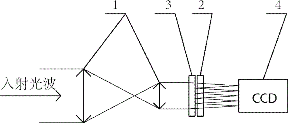
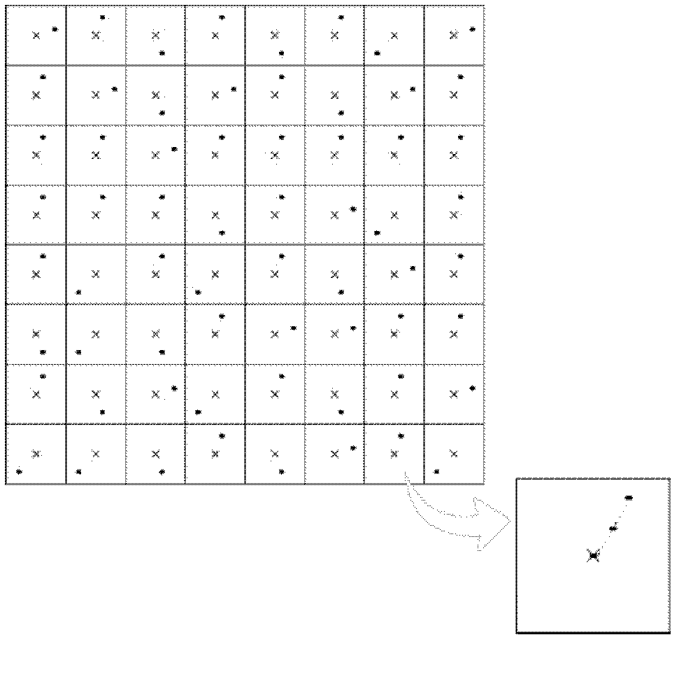
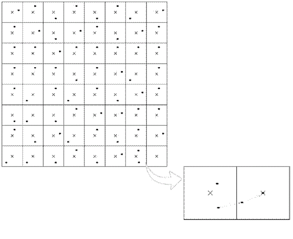
[0018] Such as figure 1 As shown, the component for compensating the wavefront aberration in the sub-aperture adopts the transmissive phase modulator 3, which is located before the wavefront division sampling array 2, and compensates the oblique aberration of the sub-wavefront in each sub-aperture. It includes an optical matching system 1, a wavefront division sampling array 2, transmissive phase modulator 3 and photoelectric sensor 4, the incident light wave is narrowed by the optical matching system 1, and passes through the transmissive phase modulator 3 before entering the wavefront split sampling array 2, the transmissive phase modulator can adjust the light wave Adding specific aberrations, the sub-apertures of the wavefront split sampling array 2 divide the light wave into many sub-beams, the focal plane of which coincides with the target surface of the photoelectric sensor 4, and the sub-beams in each sub-aperture are respectively focused on the target surface of the ph...
Embodiment 2
[0037] Such as Figure 4 As shown, the wavefront aberration compensation element in the sub-aperture adopts a transmissive phase modulator 3, which is located before the wavefront division sampling array 2 before the optical matching system, and compensates the wavefront aberration in each sub-aperture, which includes an optical matching system 1, a wavefront The front split sampling array 2, the transmissive phase modulator 3 and the photoelectric sensor 4, the incident light wave enters the wave front split sampling array 2 after being narrowed by the optical matching system 1, and the sub-aperture of the wave front split sampling array 2 splits the light wave into many sub-apertures The focal plane of the light beam coincides with the target surface of the photoelectric sensor 4, and the sub-beams in each sub-aperture are respectively focused on the target surface of the photoelectric sensor 4. The transmissive phase modulator is placed before the optical matching system, an...
PUM
 Abstract
Description
Claims
Application Information
 - R&D
- Intellectual Property
- Life Sciences
- Materials
- Tech Scout
- Unparalleled Data Quality
- Higher Quality Content
- 60% Fewer Hallucinations
Browse by: Latest US Patents, China's latest patents, Technical Efficacy Thesaurus, Application Domain, Technology Topic, Popular Technical Reports.
© 2025 PatSnap. All rights reserved.Legal|Privacy policy|Modern Slavery Act Transparency Statement|Sitemap|About US| Contact US: help@patsnap.com


