Wall switch of LED (Light-emitting Diode) lamp

A wall switch and LED lamp technology, applied in the direction of electric switch, lamp circuit layout, lighting device, etc., can solve the problems of low efficiency, charged metal shell, danger, etc., and achieve the effect of easy control, easy maintenance and replacement

Inactive Publication Date: 2012-04-25
柴宏力
View PDF0 Cites 8 Cited by
  • Summary
  • Abstract
  • Description
  • Claims
  • Application Information

AI Technical Summary

Problems solved by technology

[0003] The main function of the LED lighting power supply is to convert the AC voltage into a constant current output. There are mainly two types: isolated type and non-isolated type. The isolated type power supply uses an isolation transformer to isolate the AC input from the LED driver, avoiding the danger of electric shock to a certain extent. However, due to its large size and low efficiency, it is not widely used. The non-isolated power supply is not completely electrically isolated from the input and output terminals. If the measures are not taken properly, the metal casing will also be charged, which is very dangerous.
[0004] In order to facilitate the replacement of traditional light sources, LED lamps usually have the same shape as traditional lamps. In this way, the built-in power supply must be adopted, that is, the power supply, LED and aluminum substrate are assembled inside the LED lamp shell, and the small space inside Unable to accommodate a large power supply, the components of the power supply can only be simplified, resulting in performance degradation. At the same time, the heat generated by the power supply also adds an additional burden to the heat dissipation of LED lamps. In order to add functions such as dimming and color matching, it is necessary to add circuits to the power supply. , so that the size is too large to be placed inside the lamp. If the power supply or light source is damaged, the entire lamp has to be disassembled, which is not easy to maintain and replace

Method used


Image

  • Wall switch of LED (Light-emitting Diode) lamp
  • Wall switch of LED (Light-emitting Diode) lamp
  • Wall switch of LED (Light-emitting Diode) lamp

Examples


Embodiment Construction

[0013] In order to facilitate understanding of the purpose, function and effect of the present invention, in conjunction with accompanying drawing, embodiment is described as follows:

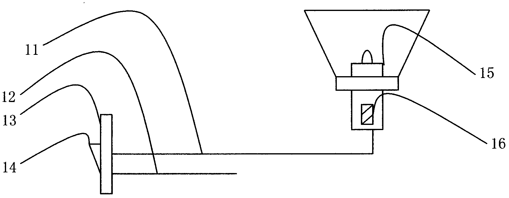
[0014] Such as figure 1 As shown, it is a schematic diagram of the switch connection of common LED lamps, including AC output line 11, AC input line 12, common wall switch 13, button 14, LED15 and built-in power supply 16, wherein the AC input line 12 connects the external electrical After the ordinary wall switch 13 is switched, the AC output line 11 connects the electricity to the built-in power supply 16 inside the LED lamp, and the built-in power supply 16 outputs a constant current to supply power to the LED15.

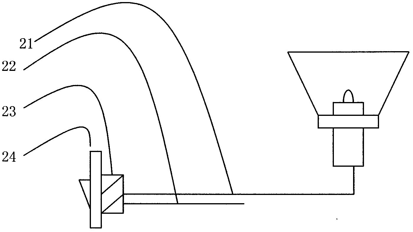
[0015] Such as figure 2 As shown, it is a schematic diagram of the switch connection of the present invention, including a DC output line 21, an AC input line 22, a power supply 23 of the wall switch and a wall switch 24, wherein the AC input line 22 connects the external electr...


PUM


Abstract

The invention relates to a wall switch of an LED (Light-emitting Diode) lamp, in particular to a wall switch for illumination of an indoor LED (Light-emitting Diode) lamp. The wall switch is mainly characterized by comprising a flame-retardant plastic shell, at least one press button or one knob which is placed on a switch surface panel, a direct-current and alternative-current switching power supply panel which is placed inside the switch, at least one constant-current drive power supply panel which is placed inside the switch, at least two clamping grooves which are fixedly arranged on the inner surface of the switch through screws, an alternative-current input terminal and at least one direct-current output terminal which are placed at the inner side of a back panel of the switch, wherein the flame-retardant plastic shell is provided with a net hole and an inner heating element is radiated through the net hole; the press button or the knob is provided with an indication lamp for displaying a work state of the constant-current power supply panel. The wall switch of the LED lamp provided by the invention has the advantages that: the drive power supply of the LED lamp is installed in the wall switch and is separated from a lamp body, so that the LED lamp is convenient to control; meanwhile, the LED lamp is convenient to maintain and exchange and the LED lamp body does not have dangers of electric shocks.

Description

technical field [0001] The present invention relates to a wall switch for LED lamps, in particular to a wall switch suitable for LED bulb lamps, LED chandeliers, LED fluorescent lamps, and LED ceiling lamps for indoor lighting. Due to the introduction of the wall switch, the drive of LED lamps The separation of the power supply and the lamp body facilitates the control of the LED lamp, and also facilitates the maintenance and replacement of the LED lamp, and also makes the LED lamp body no longer have the risk of electric shock. Background technique [0002] Light Emitting Diode (LED, Light Emitting Diode) is a PN-type semiconductor diode that uses current to emit light. When a forward voltage is applied, electrons flow into the P-type semiconductor, holes enter the N-type semiconductor, and electrons and holes recombine to emit light. The light-emitting tube made of this principle is a light-emitting diode, and the LED lighting fixture is a combination of light-emitting dio...

Claims


Application Information

Patent Timeline
Patent Type & Authority Applications(China)
IPC IPC(8): H01H9/02H05B37/02F21Y101/02
Inventor 柴宏力
Owner 柴宏力
Why Eureka
Try Eureka