
Doherty power amplifier and method and equipment for improving power amplification efficiency of Doherty power amplifier

A technology for power amplifiers and amplifiers, applied in the field of communication, can solve the problem that the efficiency of the power amplifier is increased by less than 10%, and achieve the effect of improving the efficiency of the power amplifier and reducing power consumption

Active Publication Date: 2012-04-25
HUAWEI TECH CO LTD
View PDF4 Cites 29 Cited by
  • Summary
  • Abstract
  • Description
  • Claims
  • Application Information

AI Technical Summary

Problems solved by technology

[0004] However, the inventor found in the research that although the traditional Doherty power amplifier can keep the bias of the main power amplifier in class AB, the bias of the peak power amplifier in class C and the impedance transformation relationship unchanged, according to the system traffic Size, adjust the drain voltage or gate voltage in a timely manner to improve the efficiency of the power amplifier at low power. However, after actual measurement, the above method has a peak power fallback of 12dB, that is, when the output power of the traditional Doherty power amplifier is at low power output In the low power output range, the power amplifier efficiency is increased by less than 10%. Therefore, how to improve the power amplifier efficiency of the Doherty power amplifier in the low power output range is still of great significance to the energy saving and consumption reduction of the entire base station equipment.

Method used


Image

  • Doherty power amplifier and method and equipment for improving power amplification efficiency of Doherty power amplifier
  • Doherty power amplifier and method and equipment for improving power amplification efficiency of Doherty power amplifier
  • Doherty power amplifier and method and equipment for improving power amplification efficiency of Doherty power amplifier

Examples


Embodiment Construction

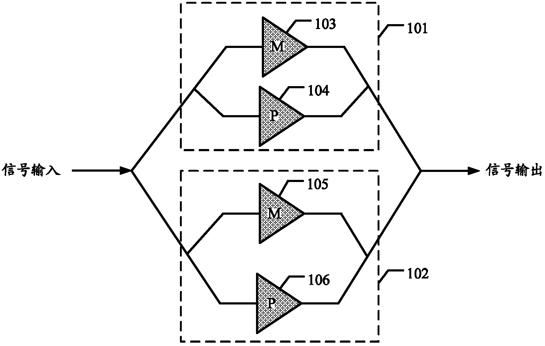
[0023] Embodiments of the present invention provide a Doherty power amplifier and a method and device for improving its power amplifier efficiency, which can effectively reduce the power consumption of the Doherty power amplifier in the low power output range and improve the power amplifier efficiency of the Doherty power amplifier.

[0024] The Doherty power amplifier structure consists of two power amplifiers: a main power amplifier and an auxiliary power amplifier. The main power amplifier works in class B or AB, and the auxiliary power amplifier works in class C. The two power amplifiers do not work in turn, but the main power amplifier works all the time, and the auxiliary power amplifier does not work until the peak value is set. The 90° quarter-wavelength line connected behind the main power amplifier is an impedance transformation, the purpose is to reduce the apparent impedance of the main power amplifier when the auxiliary power amplifier is working, and ensure that t...


PUM


Abstract

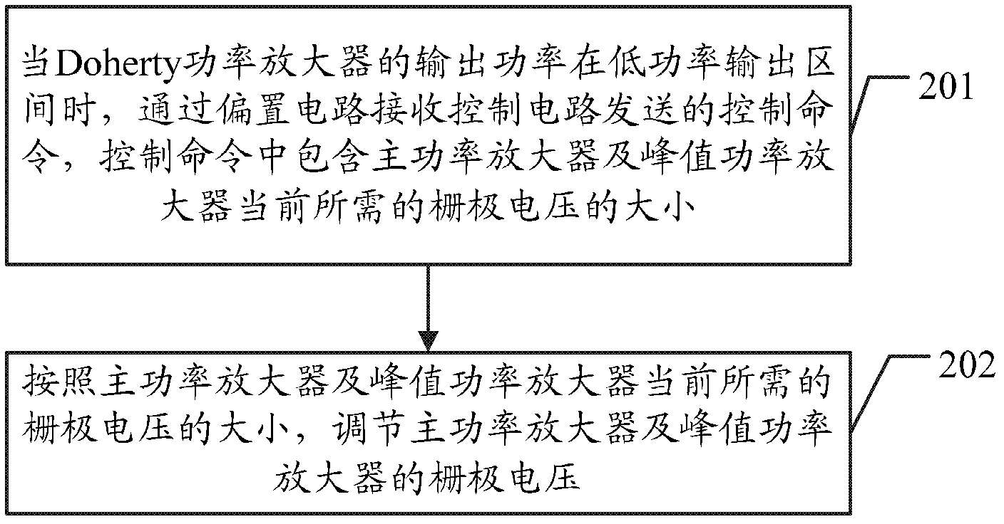
The embodiment of the invention discloses a Doherty power amplifier and a method and equipment for improving the power amplification efficiency of the Doherty power amplifier. On one hand, the invention provides the method for improving the power amplification efficiency of the Doherty power amplifier. The method is applied to the Doherty power amplifier with two parallel Doherty circuit units. Each Doherty circuit unit comprises a main power amplifier and a peak power amplifier, wherein the main power amplifier and the peak power amplifier are connected by adopting a parallel connection method. The method comprises the steps that when the output power of the Doherty power amplifier is in a low-power output interval, and the grid voltage of the main power amplifiers and the peak power amplifiers in the two parallel Doherty circuit units are regulated through a biasing circuit to enable the peak power amplifiers to be in a closed state and to enable the main power amplifiers in the two parallel Doherty circuit units to be respectively in a main power amplification state and a peak power amplification state. On the other hand, the invention additionally provides the equipment related to the method. The goals of energy saving and consumption reduction are effectively achieved.

Description

technical field [0001] The invention relates to the technical field of communication, in particular to a Doherty power amplifier and a method and equipment for improving its power amplifier efficiency. Background technique [0002] With the continuous promotion of the concept of green environmental protection and low-carbon economy in the world, operators have higher and higher requirements for the reduction of power consumption of wireless communication systems. In a wireless communication system, a radio frequency power amplifier (referred to as a power amplifier) ​​in a base station device is one of the core modules of the entire system, and an important indicator of a radio frequency power amplifier is power amplifier efficiency. Data analysis shows that in the entire base station equipment, the energy consumption of the RF power amplifier part accounts for about 60% of the total energy consumption. Improving the power amplifier efficiency of the power amplifier has beco...

Claims


Application Information

Patent Timeline
Patent Type & Authority Applications(China)
IPC IPC(8): H03F1/07
CPCH03F1/07H03F1/0288H03F1/0272H03F2200/18H03F3/24H03F3/211H03F3/245H03F2203/21106H03F2203/21142
Inventor 张希坤张亚文李松吴乔李学坤
Owner HUAWEI TECH CO LTD
Learn More