Machining process of half-pore plate

A processing technology, semi-orifice plate technology, applied in the electrical connection formation of printed components, electrical components, printed circuit manufacturing, etc., can solve the difficult problem of eliminating copper wire peaking, weak solder joints, affecting customer installation and use and other problems, to achieve the effect of improving the problem of copper skin warping and peak peak residue on the hole wall

Inactive Publication Date: 2012-04-25
金悦通电子(翁源)有限公司
View PDF3 Cites 23 Cited by
  • Summary
  • Abstract
  • Description
  • Claims
  • Application Information

AI Technical Summary

Problems solved by technology

[0004] like figure 2 As shown, using the above method, due to insufficient rotation speed and wear of the gong knife, the cutting force of the gong knife is insufficient, the bonding force between the hole copper and the hole wall is insufficient, and the ductility of the hole copper (especially after surface treatment such as hot air leveling or immersion gold, etc. Increased the thickness, ductility and toughness of the metal layer, resulting in continuous cutting) and other reasons, when cutting the copper in the electroplated hole, it will inevitably cause the copper wire to remain on the section of the remaining part of the electroplated hole. Serious There is even a phenomenon that the copper skin on the hole wall is lifted
[0005] These problems in the forming process of semi-metallized slots / holes will directly affect the installation and use of customers
The copper wire and peak remaining in the semi-metallized hole are prone to problems such as weak solder joints, virtual soldering, and bridging short circuits during the soldering process of downstream SMT manufacturers.
[0006] In order to overcome the above problems, the traditional way of thinking has always been how to improve the gong board process, such as: changing the direction of the knife, the point of the knife, and the positioning method, etc. However, these methods are difficult to eliminate the problem of copper wire covering the peak

Method used


Image

  • Machining process of half-pore plate
  • Machining process of half-pore plate
  • Machining process of half-pore plate

Examples


Embodiment Construction

[0031] The present invention will be described in detail below in conjunction with the accompanying drawings and specific implementation methods. The schematic implementation and description of the present invention are used to explain the present invention, but are not intended to limit the present invention.

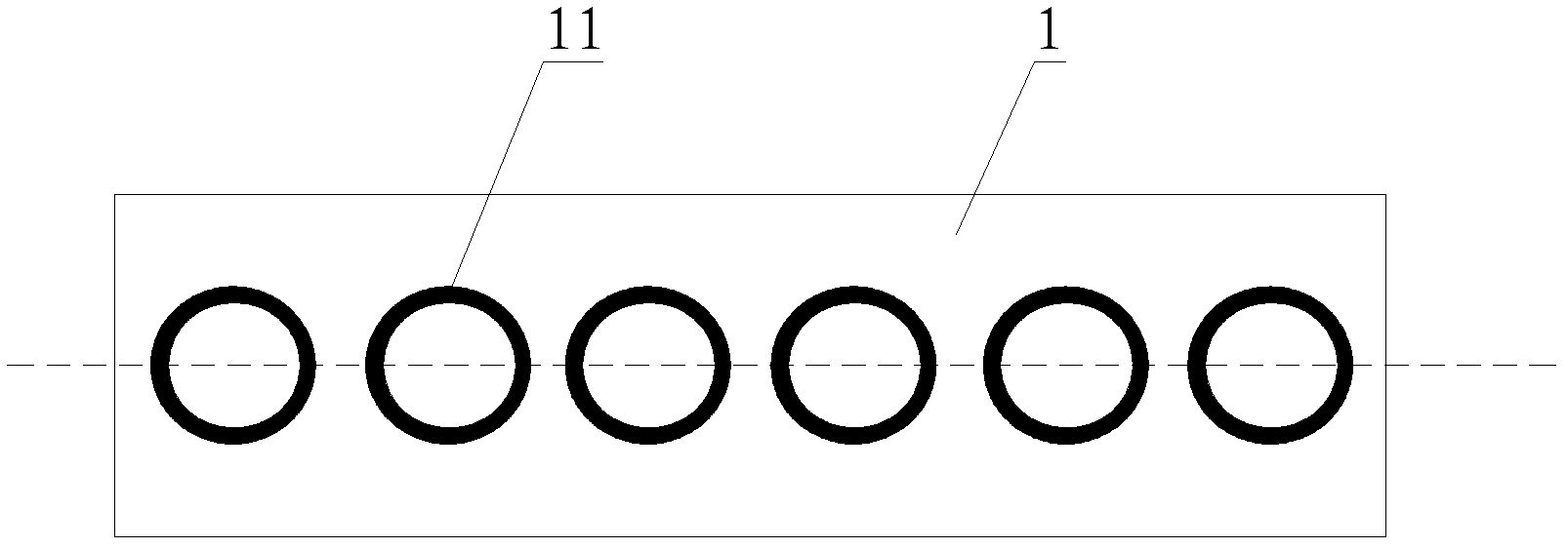
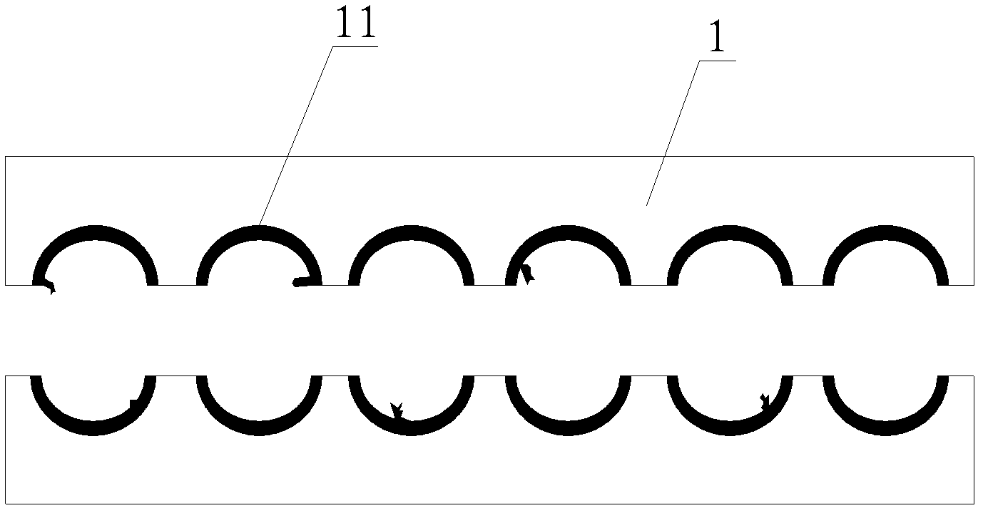
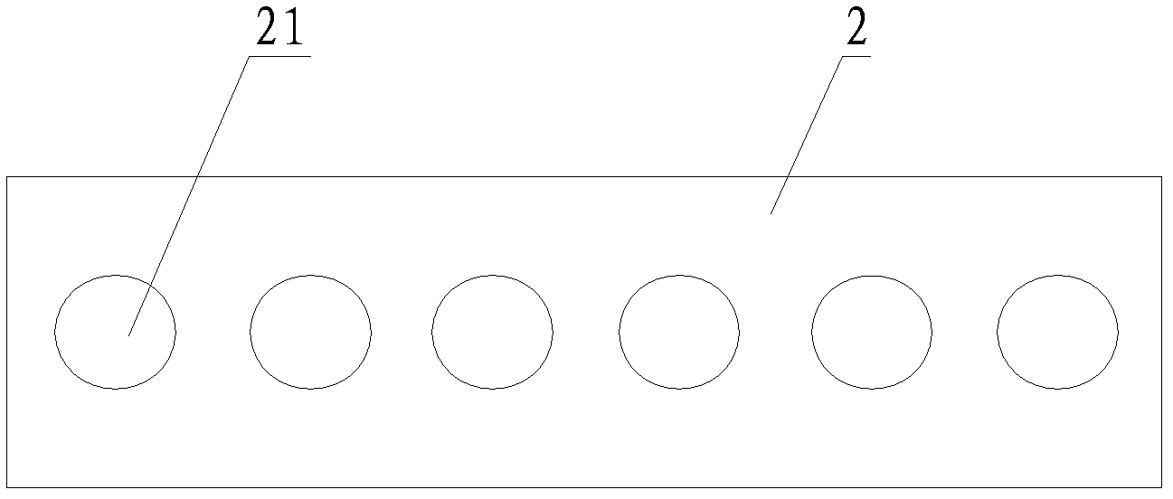
[0032] The invention discloses a processing technology of a half-hole plate, which is used for processing half-metallized grooves / holes of the half-hole plate. The production process first includes making a plug hole template 2, such as image 3 As shown, the surface of the plug hole template 2 is provided with a plurality of through holes 2. The position and size of the through holes 2 are the same as the semi-metallized grooves / holes in the half-empty board. The purpose of making the plug hole template is the same as the principle of printing technology. Protect other parts that do not require wet film plugging. Based on the convenience of processing, the material o...


PUM


Abstract

The invention belongs to the technical field of printed circuit boards (PCBs), in particular discloses a machining process of a half-pore plate, which mainly adopts a wet film pore plugging method and specifically comprises the steps of: manufacturing a pore plugging template, carrying out wet film pore plugging, baking the board, routing, retreating a film, etching and the like. Through pore plugging, ink and the half-pore plate can form an integer, pore copper on the pore wall is placed between the ink and a board pore plate body, thus the pore copper can be better protected in a routing process so that the pore copper is not easy to generate pore wall copper skin tilting and flash residual, even if less quantity of copper skin tilting and flash residual is generated, the copper tilting and the flash residual can be removed through etching. Therefore, by adopting the invention, the pore wall copper skin tilting and the flash residual of a semi-metallization groove or pore can be effectively improved.

Description

technical field [0001] The invention belongs to the technical field of printed circuit board (PCB) processing, and in particular relates to a processing technology of a half-hole board. Background technique [0002] Half-hole plate, including the so-called semi-metallized slot / hole, mostly refers to the design that only half of the metallized slot / hole is left on the PCB outline, and the other half needs to be removed during molding. Such as figure 1 as shown, figure 1 It is a schematic diagram of the edge structure when the other half of the half-hole plate has not been broken, such as figure 1 As shown, it includes a plurality of metallized holes 1 on its edge, and there are conductive hole copper 11 on the hole wall of the metallized hole 1, which is separated along the dotted line to obtain a half-hole plate. [0003] For the processing of semi-metallized grooves / holes of half-plate holes, the general forming processing methods are nothing more than CNC gong bed gong ...

Claims


Application Information

Patent Timeline
Patent Type & Authority Applications(China)
IPC IPC(8): H05K3/00H05K3/40
Inventor 罗建军
Owner 金悦通电子(翁源)有限公司
Why Eureka
Try Eureka