
Tool and process for processing white optical lens concave surface with diopter

A technology for optical lenses and leucovorans, applied in optical surface grinders, metal processing equipment, manufacturing tools, etc., can solve problems such as environmental pollution, damage to human respiratory function, and adverse production costs, so as to reduce production costs and avoid health problems. damage, improve productivity

Inactive Publication Date: 2012-05-02
王昊平
View PDF6 Cites 5 Cited by
  • Summary
  • Abstract
  • Description
  • Claims
  • Application Information

AI Technical Summary

Problems solved by technology

However, this tooling and process of "optical lens white sheet low-temperature alloy upper and lower plate" has the above advantages, but at the same time has the following disadvantages: (1) The whole process is relatively complicated, requiring more manpower materials, time-consuming and labor-intensive, resulting in waste of manpower and resources. At the same time, the production efficiency is also low; (2) after the lens processing is completed, when the lens is separated from the protective film, the protective film is not easy to peel off, which affects production efficiency; (2) the cost of the low-temperature alloy used is expensive, and the price of non-ferrous metals in the alloy fluctuates greatly, increasing At the same time of production cost, it is not conducive to control the production cost; (3) low-temperature alloy itself is not environmentally friendly and pollutes the environment, and the low-temperature alloy contains metal indium, which is toxic to the human body. Long-term inhalation of powder containing indium will cause damage to human respiratory function , is detrimental to the health of the operator

Method used


Image

  • Tool and process for processing white optical lens concave surface with diopter
  • Tool and process for processing white optical lens concave surface with diopter
  • Tool and process for processing white optical lens concave surface with diopter

Examples


Embodiment 1

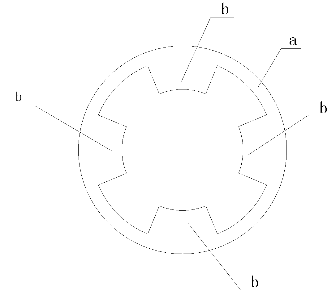
[0043] This embodiment is a kind of optical lens white film diopter concave processing tooling, which has a disc-shaped main body and double-sided adhesive stickers. Such as figure 1 As shown, the double-sided adhesive tape has a narrow ring a attached to the peripheral edge of the bottom surface of the disc-shaped main body, and the narrow ring a is connected with two pairs of fan-shaped tabs that are symmetrically distributed and point to the center of the bottom surface of the disc-shaped main body. b, the fan-shaped protruding piece b is pasted within the narrow ring a on the bottom surface of the disc-shaped main body.

[0044] Use the technical method of the optical lens white sheet diopter concave processing tooling of the present embodiment, carry out according to the following steps:

[0045] (1) Paste the disc-shaped main body on the white side of the optical lens with the help of double-sided adhesive tape;

[0046] (2) Clamping the disc-shaped main body on a grin...

Embodiment 2

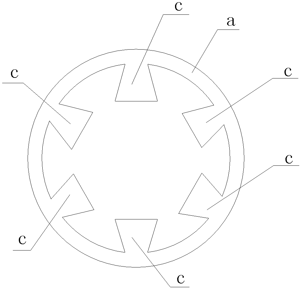
[0049] This embodiment is similar to Embodiment 1, the difference lies in the shape of the protruding piece, the protruding piece of this embodiment is a trapezoidal protruding piece c, and the narrow ring a is connected with three pairs that are symmetrically distributed and point to the center of the bottom surface of the disc-shaped main body. The trapezoidal lug c is pasted within the narrow ring a on the bottom surface of the disc-shaped main body.

[0050] The processing method of using the diopter concave surface processing tool of the optical lens white sheet of this embodiment is the same as that of Embodiment 1.

Embodiment 3

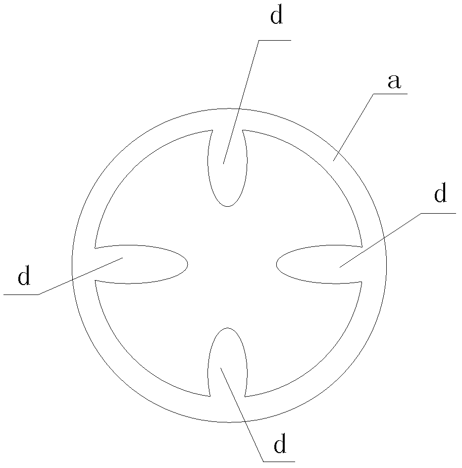
[0052] This embodiment is similar to Embodiment 1, the difference lies in the shape of the protruding piece, the protruding piece of this embodiment is an elliptical protruding piece d, and there are two pairs of symmetrically distributed pointing to the center of the bottom surface of the disc-shaped main body connected to the narrow ring a The elliptical convex piece d, the elliptical convex piece d is pasted within the narrow ring a of the bottom surface of the disc-shaped main body.

[0053] The processing method of using the diopter concave surface processing tool of the optical lens white sheet of this embodiment is the same as that of Embodiment 1.


PUM


Abstract

The invention belongs to the technical field of the production of optical lenses and provides a tool and process for processing a white optical lens concave surface with diopter. The tool is provided with a disc-shaped main body; the circumference of the bottom surface of the disc-shaped main body is provided with flanged edges; raised sphere-crown shaped hollow cavities are formed in the flangededges; the middle part of the upper surface of the disc-shaped main body is provided with a central hole which is communicated with the sphere-crown shaped hollow cavities; two sides of the central hole are at least provided with an air inlet respectively, and the air inlets are communicated with the sphere-crown shaped hollow cavities; a circle of double-sided adhesive tape with matchable width is adhered to the bottom surface of each flanged edge; the sphere-crown shaped hollow cavities are internally provided with suction discs which match with the sphere-crown shaped hollow cavities in shape; the middle parts of the suction discs are provided with air inlet and outlet pipes which penetrate out from the central hole; and the air inlet and outlet pipes are internally provided with one-way valves which can ensure that air circulates from the inside of the suction discs to the outside under the action of negative pressure. In the invention, the double-sided adhesive tapes are adopted to obtain anti-sliding power, the suction discs are adopted to obtain anti-peel force, the white optical lens can be fixed firmly without falling off when being processed and can be peeled easily after being processed without being scratched or polluted on the surface. In the invention, the low-temperature alloy is not used, the production cost is reduced, the production efficiency is improved, the damage to the health of the operators is avoided, and the pollution to the environment is prevented.

Description

technical field [0001] The invention belongs to the technical field of optical lens production, and relates to the processing of the diopter of the optical lens, in particular to an optical lens white sheet diopter concave processing tool for fixing the optical lens white sheet to a grinding machine and a process method thereof. Background technique [0002] In the whole process of optical lens production, there is a white diopter concave surface processing process. The purpose is to polish one side of the resin or glass lens into a concave surface with a certain diopter. The specific processing process is to first fix the convex surface of the optical lens white film on the Fix the fixture on a grinding machine, and use the grinding machine to grind the other side of the resin or glass lens into a concave surface with a certain diopter. Among them, the process of "fixing the convex surface of the optical lens white sheet on the fixture" is called "optical lens white sheet u...

Claims


Application Information

Patent Timeline
Patent Type & Authority Applications(China)
IPC IPC(8): B24B13/00B24B13/005
Inventor 王昊平
Owner 王昊平
Learn More