Exhaust line for an internal combustion engine

An exhaust pipe, internal combustion engine technology, applied in exhaust devices, mechanical equipment, engine components, etc., can solve problems such as increasing the complexity of exhaust pipes, achieve short response time, reduce weight and cost, and reduce complexity Effect

Inactive Publication Date: 2012-05-02
MAN DIESEL & TURBO SE
View PDF6 Cites 0 Cited by
  • Summary
  • Abstract
  • Description
  • Claims
  • Application Information

AI Technical Summary

Problems solved by technology

[0003] In such exhaust pipes, corresponding connecting elements (such as flanges or clamp connections (Spannschellenanschluss)) must be provided for each connection of the deformation compensation element, which increases the complexity of the exhaust pipe

Method used


Image

  • Exhaust line for an internal combustion engine
  • Exhaust line for an internal combustion engine
  • Exhaust line for an internal combustion engine

Examples


Embodiment Construction

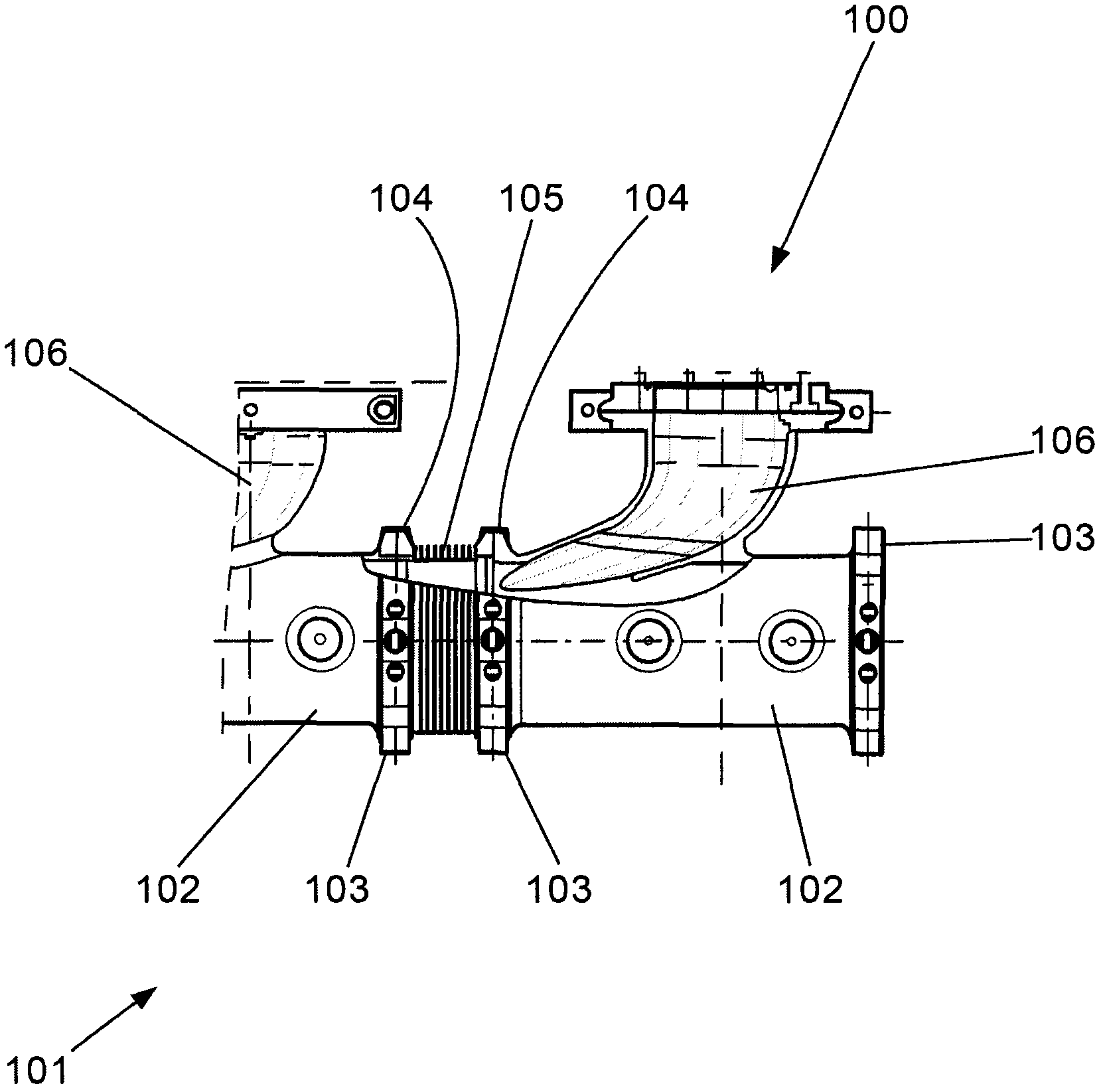
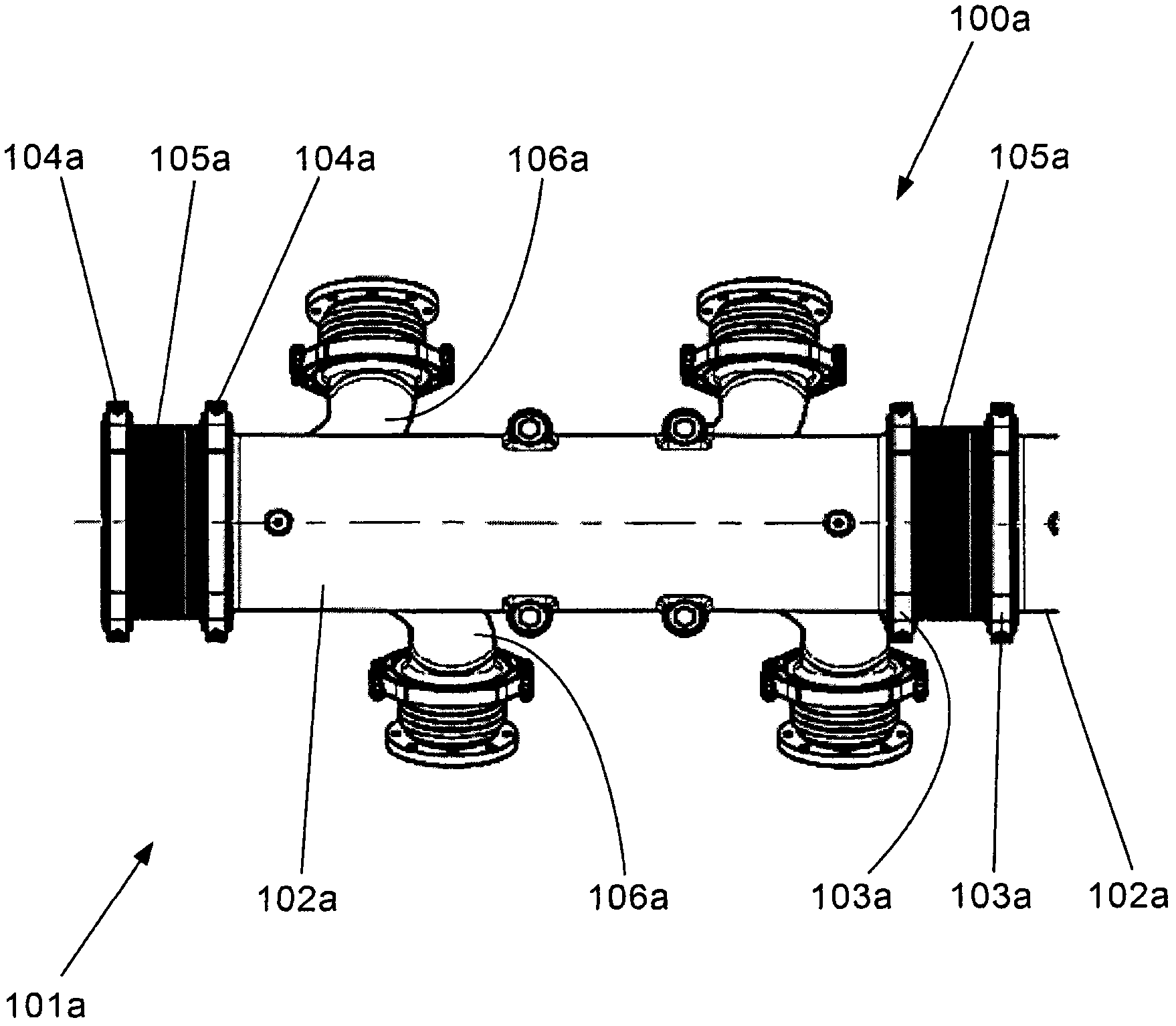
[0066] figure 1 with figure 2 Two examples of exhaust pipes 100, 100a for internal combustion engines (not shown) manufactured to date by the applicant are shown.

[0067] Such as figure 1 As shown, the exhaust pipe 100 has a line arrangement 101 with a plurality of individual pipe segments 102 made of, for example, cast iron. Within the longitudinal extension of the line arrangement 101, a deformation compensation element 105 is arranged between two adjacent pipe sections 102 (in the figure 1 Only one deformation compensator is shown in ) for absorbing the deformation of the line set 101 . In order to connect the individual pipe sections 102 and deformation compensators 105 , clamping clip couplings 103 are respectively provided at the respective longitudinal ends of these components, which are joined together with clamping clips 104 .

[0068] Each pipe segment 102 has, laterally on its wall, a cylinder connection 106 for the exhaust gas of a cylinder (not shown) of an ...


PUM


Abstract

An exhaust line for an internal combustion engine is provided to simplify a structure by integrally forming one or more strain compensation units in a pipe line. An exhaust line (1) for an internal combustion engine comprises a pipe line (10) and one or more strain compensation units (20). The pipe line comprises one or more cylinder connection units (40) for exhaust gas. The strain compensation units are integrally arranged on the pipe line in a longitudinal direction and accept the strain of the pipe line.

Description

technical field [0001] The invention relates to an exhaust pipe for an internal combustion engine designed according to the preamble of claim 1 . Background technique [0002] An exhaust pipe of the type mentioned at the outset is known, for example, from document US 2 014 355A. In this exhaust pipe, the line arrangement (Rohrleitungsanordnung) has a deformation compensator designed as a separate component, which is inserted into the line arrangement via a threaded flange in such a way that it makes both of the line arrangement Adjacent individual pipe sections are detachably connected to each other. [0003] In such exhaust pipes, corresponding connecting elements (such as flanges or clamp connections (Spannschellenanschluss)) have to be provided for each connection of the deformation compensator, which increases the complexity of the exhaust pipe . Contents of the invention [0004] It is therefore the object of the invention to provide an exhaust pipe according to th...

Claims


Application Information

Patent Timeline
IPC IPC(8): F01N13/08
CPCF01N13/10F01N13/1816F16L39/04F16L51/02
Inventor M·比尔H-P·格拉夫
Owner MAN DIESEL & TURBO SE
Why Eureka
Try Eureka