
Foam plastic machine hydraumatic station

A technology of hydraulic station and foam molding machine, which is applied in the direction of mechanical equipment, fluid pressure actuation device, fluid pressure actuation system components, etc., and can solve the problem that the hydraulic station of foam molding machine cannot meet the requirements of rapid feeding of the system. Problems such as poor energy saving effect of the station

Inactive Publication Date: 2012-05-02
大连维乐液压制造有限公司
View PDF4 Cites 5 Cited by
  • Summary
  • Abstract
  • Description
  • Claims
  • Application Information

AI Technical Summary

Problems solved by technology

[0002] In the prior art, the hydraulic station of the foam molding machine cannot meet the requirements of fast feed and pressure requirements of the system, so the energy saving effect of this hydraulic station is poor

Method used


Image

  • Foam plastic machine hydraumatic station
  • Foam plastic machine hydraumatic station
  • Foam plastic machine hydraumatic station

Examples


Embodiment Construction

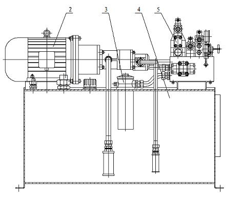
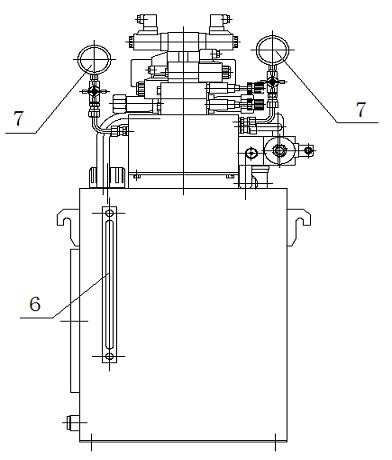
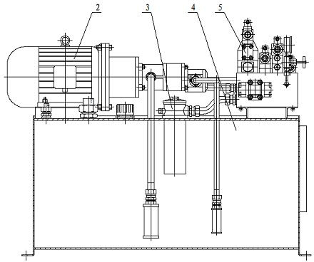
[0011] Such as figure 1 , figure 2 As shown, the hydraulic station of the foam molding machine includes the high oil tank control valve group 1, the power pump 2, the auxiliary components 3, the fuel tank 4 and the hydraulic station control valve group 5, the high oil tank control valve group 5, the power pump 2, and the auxiliary components 3 and the control valve group 5 of the hydraulic station are arranged on the top of the oil tank 4, the power pump 2 is connected to the control valve group 5 of the hydraulic station through pipelines, the auxiliary component 4 is connected to the control valve group 5 of the hydraulic station, and the side wall of the oil tank 4 is installed with a liquid level Meter 6, the power pump 2 is equipped with a pressure gauge 7, the flow of the pump is consistent with the flow required by the speed of the actuator, the hydraulic system of the foam molding machine makes the flow of the hydraulic pump only half of the flow required by the speed...


PUM


Abstract

The invention discloses a foam plastic machine hydraumatic station. The foam plastic machine hydraumatic station comprises a high placing oil tank control valve group, a power pump, an auxiliary element, an oil tank and a hydraumatic station control valve group, wherein the high placing oil tank control valve group, the power pump, the auxiliary element and the hydraumatic station control valve group are arranged on the top of the oil tank; and the power pump is connected with the hydraumatic station control valve group through a pipeline, and the auxiliary element is connected to the hydraumatic station control valve group. In the foam plastic machine hydraumatic station provided by the invention, an energy-saving design method is adopted in the design of a system, when the foam plastic machine hydraumatic station is rapidly fed so as to only supply oil to two driving cylinders; the other passive cylinders are driven by the driving cylinders to charge liquid from the high placing oil tank, therefore, the working flow of the system decreases one time; and the output volume of a pump can decrease one time, the input power of the pump is reduced one time, when the hydraumatic station is inflated, and four oil cylinders are simultaneously inflated so as to meet the pressure requirements of the system.

Description

technical field [0001] The invention relates to a hydraulic station of a foam molding machine. Background technique [0002] In the prior art, the hydraulic station of the foam molding machine cannot meet the requirements of fast feed and pressure of the system, so the energy saving effect of this hydraulic station is poor. Contents of the invention [0003] The object of the present invention is to provide a hydraulic station for a foam molding machine. [0004] The technical solution adopted by the present invention to achieve the above purpose is: a foam molding machine hydraulic station, including a high fuel tank control valve group, a power pump, auxiliary components, a fuel tank and a hydraulic station control valve group, the high fuel tank control valve The power pump, auxiliary components and hydraulic station control valve group are arranged on the top of the fuel tank, the power pump is connected to the hydraulic station control valve group through pipelines, ...

Claims


Application Information

Patent Timeline
Patent Type & Authority Applications(China)
IPC IPC(8): F15B21/00
Inventor 张久海丁维力
Owner 大连维乐液压制造有限公司
Learn More