Chain

一种链条、链板的技术,应用在链条领域,能够解决增加磨损、发热噪音、张力不均衡等问题,达到抑制磨损增加、提高耐久性、抑制弯曲的效果

Active Publication Date: 2012-05-02
TSUBAKIMOTO CHAIN CO
View PDF8 Cites 3 Cited by
  • Summary
  • Abstract
  • Description
  • Claims
  • Application Information

AI Technical Summary

Problems solved by technology

[0017] According to the known chains described in Patent Documents 1, 2, etc., although the above-mentioned problem of unbalanced tension applied to the middle link plate and the inner link plate is alleviated to some extent, the bending and guiding of the connecting pin The bending problem of the chain plate has not been solved, and there is still the problem of deterioration of durability due to increased wear, heat generation and noise due to repeated deformation
[0018] In addition, since it is necessary to prepare intermediate link plates and inner link plates with different pin hole sizes and pitches, and to arrange them at correct positions, there is a problem of increased manufacturing and assembly costs.
[0019] Furthermore, since the size and pitch of the pin holes are set on the premise of a certain bending of the connecting pins, the amount of bending of the connecting pins changes as the tension of the chain changes. The tension on the chain will still be unbalanced, so the tension is concentrated on a specific chain plate, and there is a problem that the strength of the chain against tension as a whole is reduced

Method used


Image

  • Chain
  • Chain
  • Chain

Examples


Embodiment 1

[0060] Hereinafter, the chain in the Example of this invention is demonstrated based on drawing.

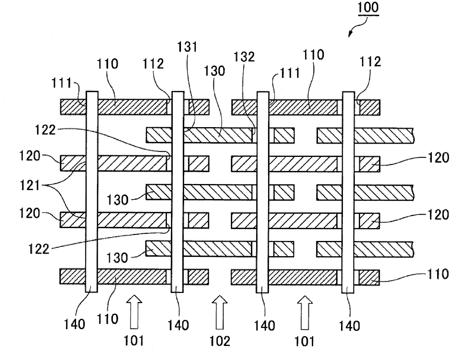
[0061] The chain 100 of the first embodiment of the present invention, as figure 1 As shown, a pair of guide chain plates 110 are arranged on the two outer sides of the width direction of the guide chain link row 101, and an intermediate chain plate 120 is arranged between the pair of guide chain plates 110 of the guide chain link row 101. Disposed in column 102 are inner link plates 130 .

[0062] A pair of front and rear first pin holes 111 , 121 , 131 and second pin holes 112 , 122 , 132 are respectively provided on the guide link plate 110 , the middle link plate 120 , and the inner link plate 130 .

[0063] Through the first pin holes 111, 121 of the guide link plate 110 and the intermediate link plate 120 of the guide link row 101 and the second pin hole 132 of the inner link plate 130 of the non-guide link row 102, and the guide link row 101 The second pin holes 112, 12...

Embodiment 2

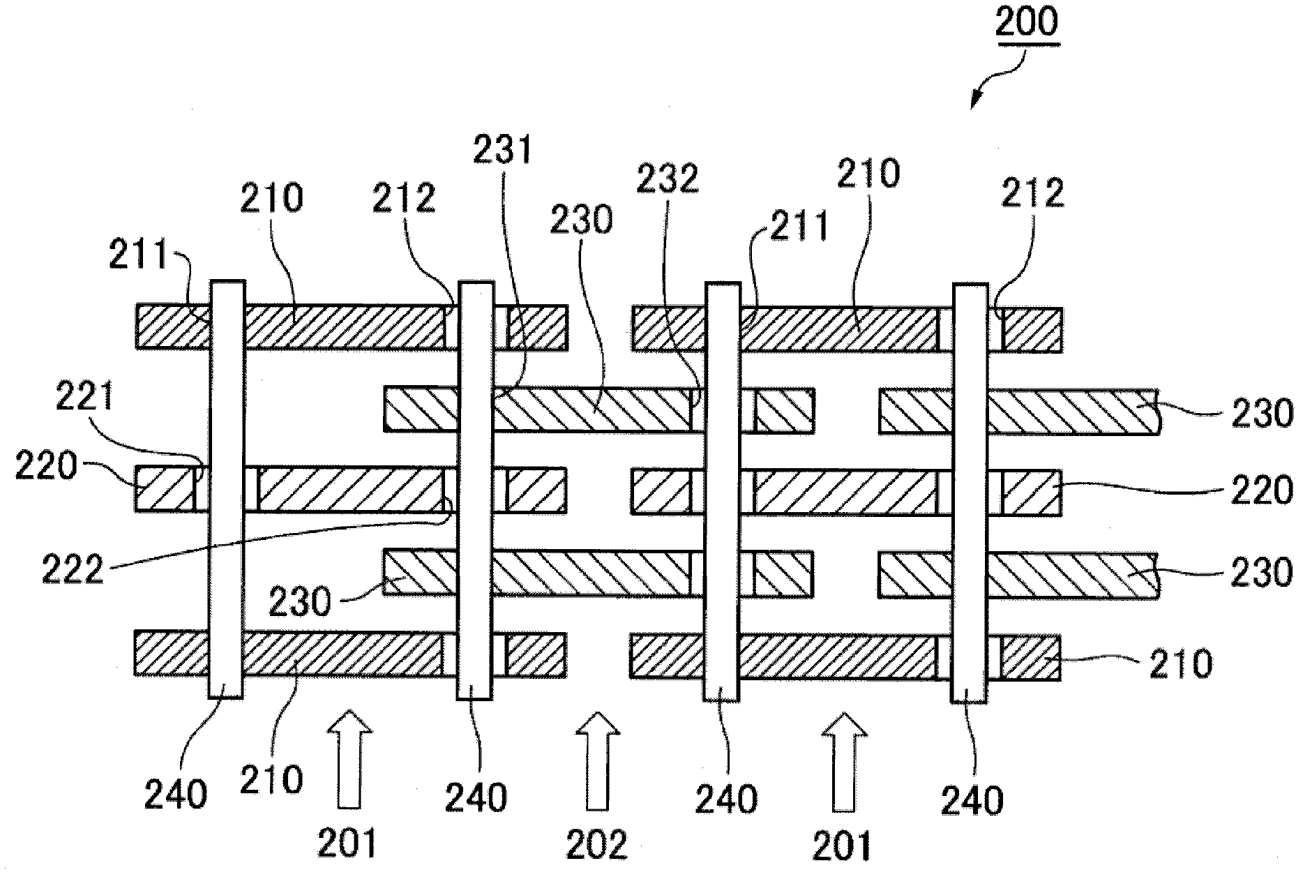
[0072] The chain 200 of the second embodiment of the present invention, as figure 2 As shown, a pair of guide chain plates 210 are arranged on both outer sides of the guide chain link row 201 in the width direction, and an intermediate link plate 220 is arranged between the pair of guide chain plates 210 of the guide chain link row 201. Disposed in column 202 are inner link plates 230 .

[0073] A pair of front and rear first pin holes 211 , 221 , 231 and second pin holes 212 , 222 , 232 are respectively provided on the guide link plate 210 , the middle link plate 220 , and the inner link plate 230 .

[0074] Through the first pin holes 211, 221 of the guide link plate 210 and the intermediate link plate 220 of the guide link row 201 and the second pin hole 232 of the inner link plate 230 of the non-guide link row 202, and the guide link row 201 The second pin holes 212, 222 of the guide chain plate 210 and the middle link plate 220 and the first pin hole 231 of the inner si...

Embodiment 3

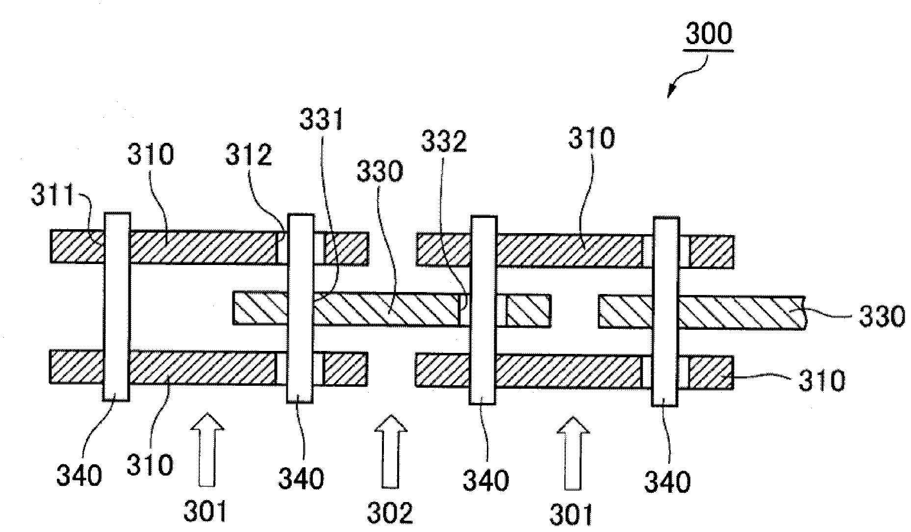
[0084] The chain 300 of the 3rd embodiment of the present invention, as image 3 As shown, a pair of guide link plates 310 are provided on both outer sides of the guide link row 301 in the width direction, and one inner link plate 330 is provided on the non-guide link row 302 .

[0085] A pair of front and rear first pin holes 311, 331 and second pin holes 312, 332 are provided on the guide link plate 310 and the inner link plate 330, respectively.

[0086] Pass through the first pin hole 311 of the guide chain plate 310 of the guide chain link row 301 and the second pin hole 332 of the inner side link plate 330 of the non-guide chain link row 302, and the first pin hole 332 of the guide chain plate 310 of the guide chain link row 301. 2. Connecting pins 340 are inserted through the pin holes 312 and the first pin holes 331 of the inner link plate 330 of the non-guide link row 302, respectively, so that the braided chain 300 is alternately connected.

[0087] The respective c...


PUM


Abstract

The invention provides a chain which can control manufacturing and assembling cost, and inhibit the wear increasing, heating and noise due to the repetitive deformation of a connecting pin and a guide link plate, and improve durability. As a tension force does not concentrated on a specific link plate, the strength of resisting tension force of an integral chain can be increased. For each guide link row, a pair of pins is provided for connecting the guide link rows (101) and non-guide link rows (102) in articulating relationship. The first connecting pin extends into first holes (111, 121, 131) of each of the guide plates of its guide link row and into and through the second hole of each link plate of an adjacent non-guide link row. The second connecting pin extends into second holes (112, 122, 132) of each of the guide plates extends into and through a first hole of each link plate of an adjacent non-guide link row. The connecting pins fit tightly into each first hole into which it extends and fits loosely in each second hole into which it extends.

Description

technical field [0001] The present invention relates to a chain in which a plurality of link plates are connected by connecting pins and a guide link plate is disposed on the outermost side. Background technique [0002] Conventionally, for example, there is known a silent chain used as a transmission chain, which has a guide link row provided with a pair of guide link plates on both outer sides in the width direction and a non-guided chain link row provided with at least one inner link plate. Chain link row; the chain plates of the guide chain link row and the non-guide chain link row have a pair of pin holes front and rear; the silent chain passes through the pin holes of the chain plate of the guide chain link row and the chain plate of the non-guide chain link row The connecting pins are respectively interspersed in the pin holes, so as to be alternately connected. [0003] Such as Figure 5 As shown, in the known chain 500, a pair of guide chain plates 510 are arranged...

Claims


Application Information

Patent Timeline
Patent Type & Authority Applications(China)
IPC IPC(8): F16G13/06
CPCF16G13/04
Inventor 本嶋良树园田腾敏森本孝之
Owner TSUBAKIMOTO CHAIN CO
Why Eureka
Try Eureka