Separable demoulding skeleton for manufacturing optic fiber loop of optic fiber gyroscope

An optical fiber loop and fiber optic gyroscope technology is applied in the field of detachable demolding skeleton, which can solve the problem that the skeleton and the optical fiber loop cannot be easily separated, and achieve the effects of high yield, high efficiency and wide application.

Active Publication Date: 2012-05-02
武汉长盈通光电技术股份有限公司
View PDF4 Cites 20 Cited by
  • Summary
  • Abstract
  • Description
  • Claims
  • Application Information

AI Technical Summary

Problems solved by technology

However, a set of this frame can only realize the preparation of a single type of frameless fiber ring, and due to

Method used


Image

  • Separable demoulding skeleton for manufacturing optic fiber loop of optic fiber gyroscope
  • Separable demoulding skeleton for manufacturing optic fiber loop of optic fiber gyroscope
  • Separable demoulding skeleton for manufacturing optic fiber loop of optic fiber gyroscope

Examples


Embodiment 1

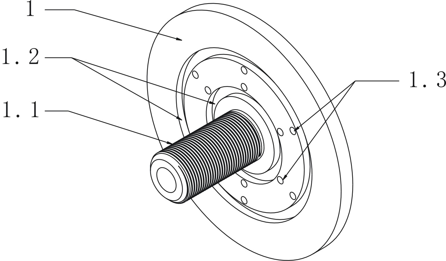
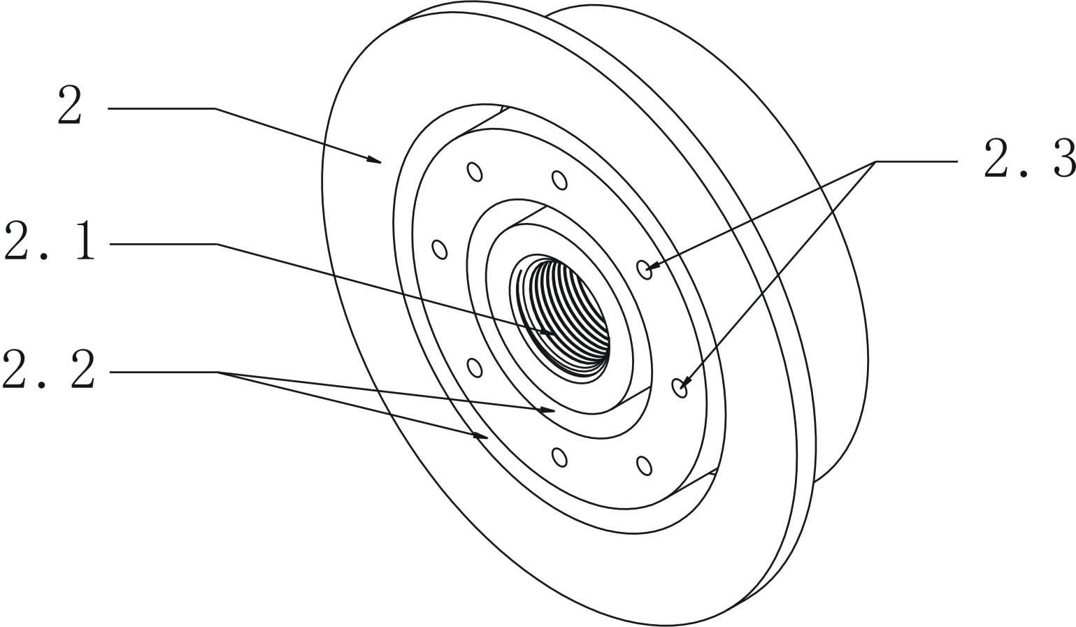
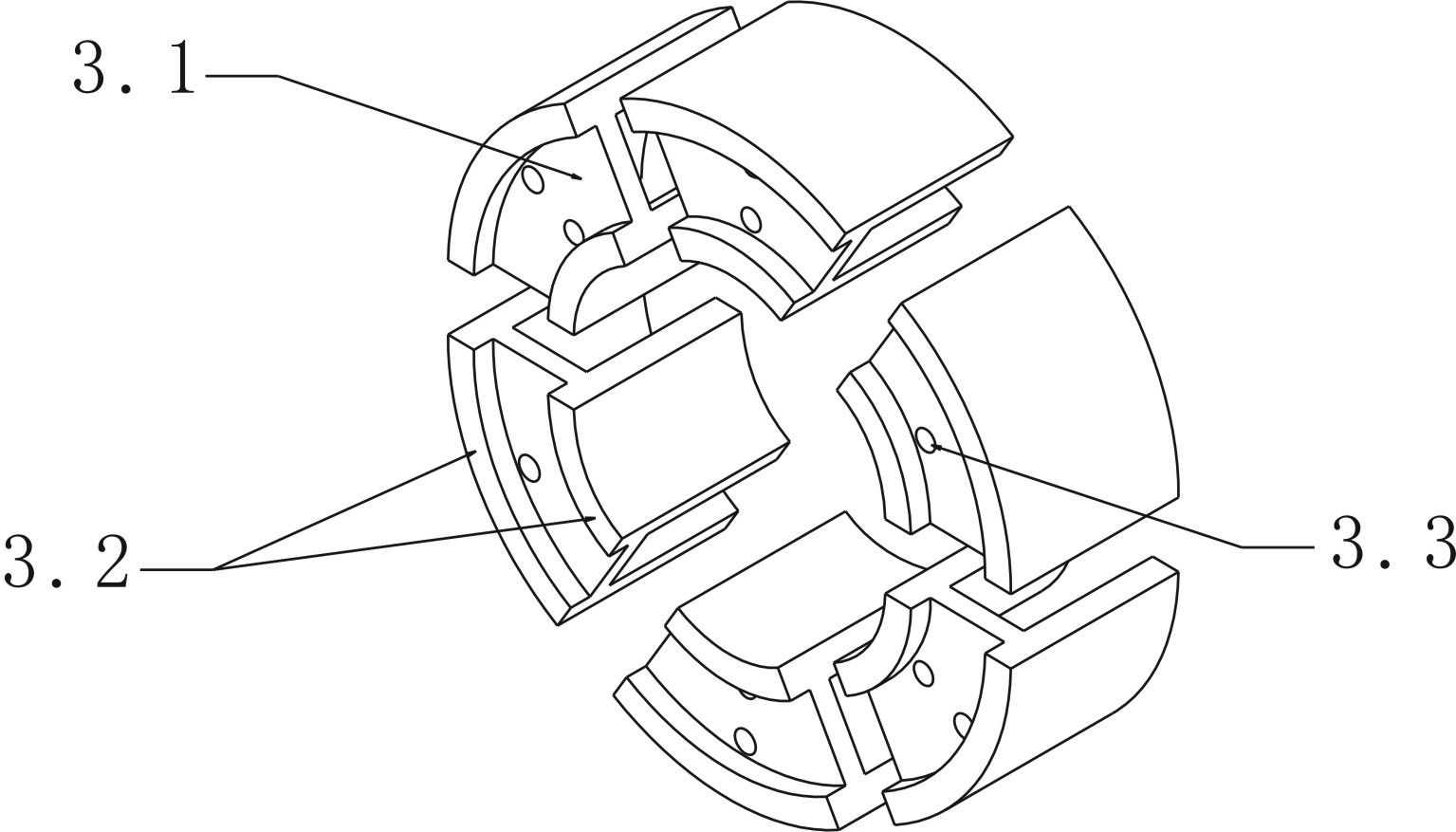
[0025] Such as Figure 1~4 and Image 6 As shown, a detachable demoulding framework for preparing fiber optic rings of fiber optic gyroscopes according to the present invention includes a first mounting plate 1, a second mounting plate 2 and a sector ring 3 composed of six sector pieces 3.1 . One side of the first installation disk 1 is provided with a hollow screw 1.1 perpendicular to the surface of the disk, six groups of twelve positioning screw holes 1.3 are evenly arranged around the hollow screw 1.1 on the first installation disk 1, and the first installation disk 1 surrounds the above-mentioned The hollow screw 1.1 is also provided with two first annular grooves 1.2. The second mounting plate 2 is provided with a screw hole 2.1 matched with the above-mentioned hollow screw rod 1.1, and two second annular grooves 2.2 are arranged around the screw hole 2.1 on it. In this embodiment, the second annular groove 2.2 is larger than the first annular groove. 1.2 deep, so tha...

Embodiment 2

[0029] Such as Figure 1~2 , Figure 5~6 As shown, another detachable demolding frame for preparing the fiber ring of the fiber optic gyroscope according to the present invention includes a first mounting plate 1 , a second mounting plate 2 and a fan ring 3 . Among them, the structure of the first installation disk 1 and the second installation disk 2 is the same as that of the first embodiment, the difference mainly lies in the fan ring 3, the fan ring 3 is composed of two fan pieces 3.1, the flange 3.2 and the opening method It is also the same as the first embodiment, after the sector ring 3 is fixed on the first mounting plate 1, there is a gap of about 3 mm between the two sector pieces 3.1.


PUM

PropertyMeasurementUnit
Thicknessaaaaaaaaaa

Abstract

The invention discloses a separable demoulding skeleton for manufacturing an optic fiber loop of an optic fiber gyroscope, comprising a first installation disc, a second installation disk, and a fan ring consisting of at least two fan blades, wherein, one side of the first installation disc is provided with a hollow screw rod which is vertical to the disc surface, a plurality of location screw holes are uniformly arranged around the hollow screw rod on the first installation disc, at least one first circular groove is arranged around the hollow screw rod on the first installation disc; a screw hole matching with the hollow screw rod is arranged on the second installation disc, at least one second circular groove is arranged around the screw hole on the second installation disc, and the second installation disc is provided with a plurality of fixed screw holes; two sides of the fan ring are respectively provided with flanges matching with the first circular groove and the second circular groove, the fan ring is provided with mounting holes corresponding to the location screw holes for fixing the fan ring on the first installation disc. The invention overcomes the various stress influences brought by the presence of the skeleton in the traditional scheme, and is suitable for preparing optic fiber loops having various widths.

Description

technical field [0001] The invention relates to an optical fiber gyroscope, in particular to a detachable stripping frame for preparing an optical fiber ring of an optical fiber gyroscope. Background technique [0002] Fiber optic gyroscope is a high-precision inertial sensor for measuring attitude and orientation. It has been widely used in robots, ships, aircraft, Missiles and many other fields. Depending on the model of the fiber optic gyroscope, it is often necessary to prepare various fiber optic loops with different specifications. The traditional fiber optic ring preparation method is to directly wind the fiber and fix it on the frame, which not only limits the layout of other components in the fiber optic gyroscope, but also restricts the further reduction of the size and weight of the fiber optic gyroscope. More importantly, due to The thermal expansion mismatch between the fiber optic ring and the skeleton will lead to stress changes in the fiber optic gyroscope ...

Claims


Application Information

Patent Timeline
IPC IPC(8): G01C25/00
Inventor 郭伟华汪洪海皮亚斌
Owner 武汉长盈通光电技术股份有限公司
Why Eureka
Try Eureka