

Pressure sensor, in particular for a braking apparatus
A pressure sensor, pressure technology, applied in the direction of brake, measuring device, measuring fluid pressure, etc., to achieve the effect of long service life and saving structure space
- Summary
- Abstract
- Description
- Claims
- Application Information
AI Technical Summary
Problems solved by technology
Method used
Image

Examples
Embodiment Construction
[0021] next reference Figures 1 to 7 A pressure sensor 1 according to a preferred embodiment of the invention will be described in detail.
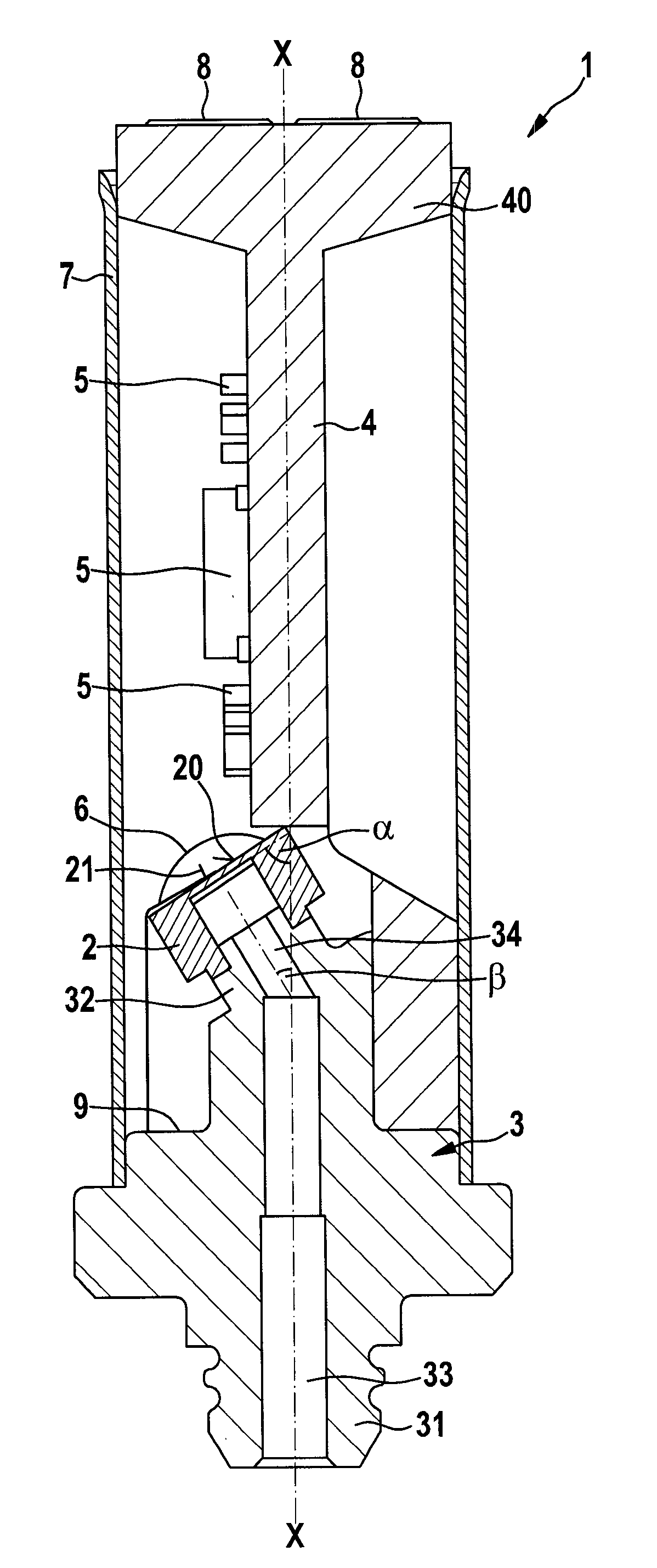
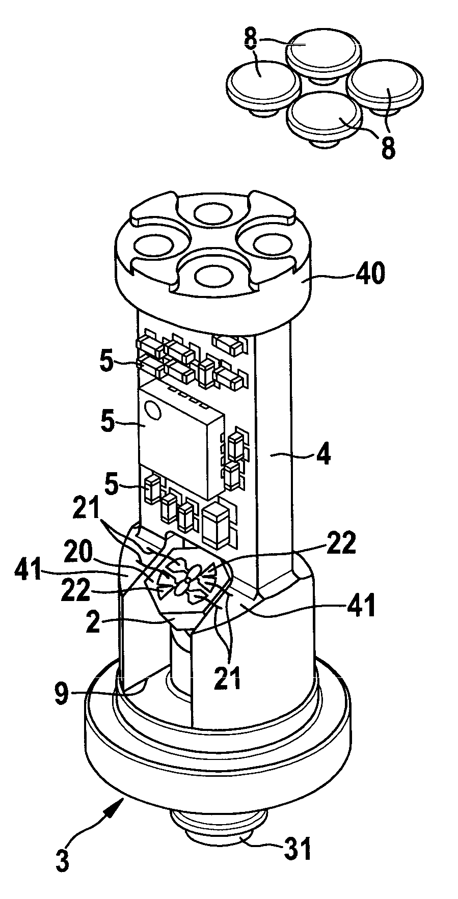
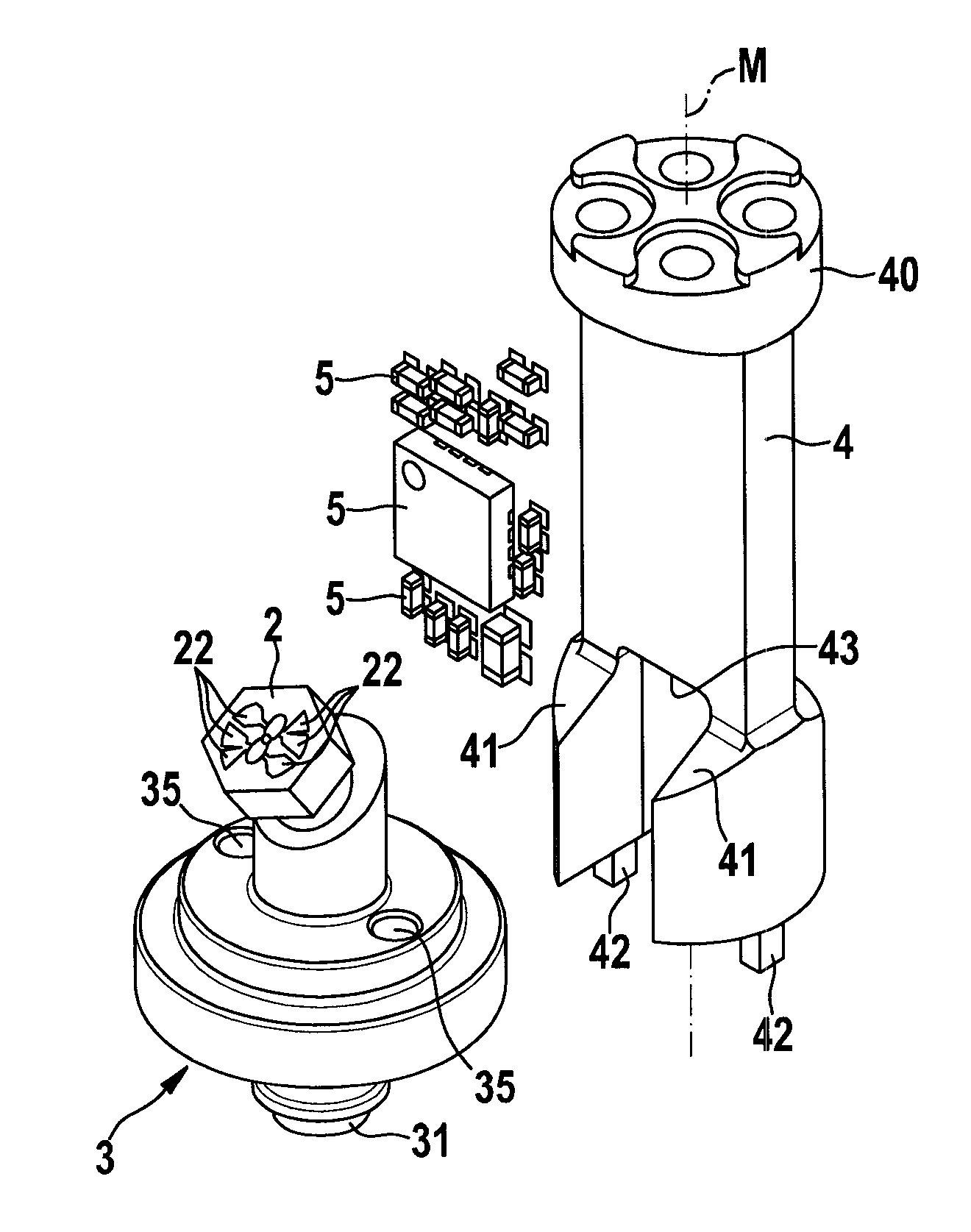
[0022] Depend on figure 1 It can be seen that the pressure sensor 1 includes a pressure measurement unit 2 and a connecting flange 3 . The connecting flange 3 has a port 31 , in which a fluid channel 33 runs, via which the medium whose pressure is to be measured is fed. The fluid channel 33 has an angled fluid channel section 34 . A receptacle 32 for accommodating the pressure-measuring cell 2 is provided at the end of the bent fluid channel section 34 . The connecting flange 3 is connected to a hydraulic system (not shown) via a port 31 .
[0023] Furthermore, the pressure sensor 1 comprises a circuit carrier 4 on which a plurality of electronic components 5 are arranged. pressure measuring cell 2 especially as figure 2 It is shown hexagonally shaped and has a contact surface 20 on which a plurality of contacts 22 are designed. ...
PUM
 Abstract
Description
Claims
Application Information