

Gas pressure gauge with automatic pressure alarming function
A gas pressure and pressure technology, applied in the field of pneumatic system detection, can solve the problems of wide range of pipeline layout and troublesome pressure detection
Inactive Publication Date: 2012-05-02
北京爱索能源科技股份有限公司
View PDF4 Cites 4 Cited by
- Summary
- Abstract
- Description
- Claims
- Application Information
AI Technical Summary
Problems solved by technology
However, the pipeline layout of the pneumatic system has a wide range, covering every corner of the factory's gas consumption
The pressure detection of this pipeline brings some trouble
Method used
View moreImage
Smart ImageViewing Examples

Examples
Embodiment Construction
[0020] The present invention will be further described below.
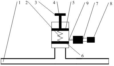
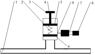
[0021] Connect the instrument in parallel to the pipeline, turn the knob to set the maximum pressure allowed in the pipeline, and the maximum pressure at this time corresponds to the spring preload. When the gas pressure is greater than the maximum pressure, the gas pushes the lower pressure plate (6), the gas in the pipeline flows out from the overflow hole (9), enters the gas amplifier (7), and finally drives the gas alarm (8) to alarm.
Login to View More PUM
 Abstract
The invention belongs to the field of detection on pneumatic systems and realizes a gas pressure gauge with an automatic alarming function. The automatic alarming pressure gauge is arranged in a gas pipeline system and can automatically send out sound when the pressure is higher than the pressure set by the gas pressure gauge. In the invention, a mechanical equilibrium mechanism of a spring force and manifold pressure is adopted, when the manifold pressure is higher than the alarm pressure, gas overcomes the spring force to push a valve, the gas flows out from an overflow hole, and finally a gas alarm device is driven to send out sound; and meanwhile, a flow amplifier adopting a coanda effect is arranged between the overflow hole and the gas alarm device, thus the phenomenon that air flow of the overflow hole is low and can not drive the gas alarm device to send out sound is avoided. Compared with the traditional pressure instrument with an alarming function, the gas pressure gauge provided by the invention completely has the advantages that a mechanical structure manner is adopted, the structure is simple, and no external power supply is required, thus the gas pressure gauge provided by the invention is more applicable to an occasion with complex gas supply requirements and is simple to use.
Description
technical field [0001] The invention belongs to the field of pneumatic system detection and relates to a gas pressure gauge with an automatic pressure alarm function. Background technique [0002] Gas pressure sensing is one of the most commonly used techniques in pneumatic systems. The size of the gas output pressure is not only related to the smooth progress of the production process, but also the pressure detection at key positions will also affect the safety of the system. Due to the advantages of low cost, no pollution, and easy maintenance, pneumatic systems play an important role in automobile production, semiconductor manufacturing and other industries. However, the pipeline layout of the pneumatic system has a wide range, covering every corner of the factory's gas consumption. The pressure detection of this pipeline brings certain troubles. [0003] The existing domestic pressure instruments with alarm function generally transmit the pressure data to a specific a...
Claims
Login to View More Application Information
Patent Timeline
 Patent Type & AuthorityApplications(China)
IPC IPC(8): G01L19/08G01L19/12
Inventor虞启辉杜丙同李晶
Owner北京爱索能源科技股份有限公司