
Electroluminescence automatic imaging apparatus

An imaging device and electroluminescence technology, which are used in electrical excitation analysis, material excitation analysis, optical testing flaws/defects, etc., can solve the problems of uncertain judgment, visual fatigue, difficulty in rework, etc. The effect of reducing visual fatigue and fast detection speed

Inactive Publication Date: 2012-05-02
JIANGYIN XINHUI SOLAR ENERGY
View PDF7 Cites 3 Cited by
  • Summary
  • Abstract
  • Description
  • Claims
  • Application Information

AI Technical Summary

Problems solved by technology

[0004] Both of the above EL testers are limited to testing a single product: the EL tester for cells only detects cells, and the EL tester for photovoltaic modules only detects photovoltaic components
And neither of these two EL detectors can detect single-welded or series-welded cells. In fact, the welding process is most likely to cause problems with photovoltaic modules.
If the soldering process cannot be monitored well, it will be very difficult or impossible to rework when the problematic photovoltaic modules are found after the photovoltaic modules are packaged.
[0005] In addition, when the component EL tester detects the component, it takes one photo at a time, and the size of each cell in this photo will be small, and the resolution and definition will be low.
It is still difficult for inspectors to find the problem of each cell during the inspection. If a cell is suspected to be a problem in this photo, due to the small size of the cell in the photo, the problem of low resolution and clarity , it cannot be determined with certainty that
At the same time, due to long-term and careful observation, the inspectors can easily cause visual fatigue and missed inspections.

Method used


Image

  • Electroluminescence automatic imaging apparatus
  • Electroluminescence automatic imaging apparatus
  • Electroluminescence automatic imaging apparatus

Examples


Embodiment Construction

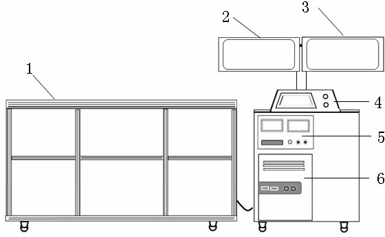
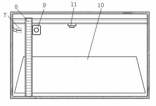
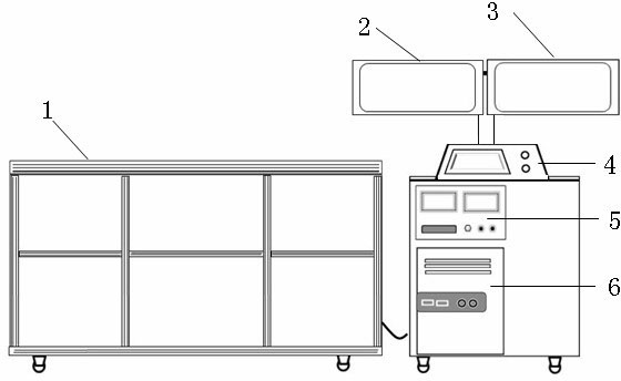
[0020] see figure 1 and figure 2 , figure 1 It is a schematic diagram of the front structure of the electroluminescent automatic imaging device of the present invention. figure 2 It is a schematic diagram of the internal structure of the electroluminescent automatic imaging device of the present invention. Depend on figure 1 and figure 2 It can be seen that the electroluminescent automatic imaging device of the present invention includes a measurement platform 1, a display I2, a display II3, a control platform 4, a current source 5, a computer 6, a current connector 7, an XY high-speed positioning system 8, a camera I9, and a mirror 10 and Camera II11.

[0021] The control platform 4 is connected with the measurement platform 1 by an optical fiber / data line, and the control platform 4 is an operating device for issuing instructions. The control platform 4 is provided with a current source 5 and a computer 6, and the control platform 4 is provided with a display I2 and...


PUM


Abstract

The invention relates to an electroluminescence automatic imaging apparatus comprising two main parts, which are a controlling platform (4) and a measuring platform (1). The controlling platform (4) and the measuring platform (1) are connected by using an optical fiber / data line. A current source (5) and a computer (6) are arranged in the controlling platform (4). A display I (2) and a display II (3) are arranged on the controlling platform (4). A current joint (7), an XY high-speed locating system (8), a camera I (9), a mirror (10) and a camera II (11) are arranged in the measuring platform (1). The current joint (7) and the current source (5) are electrically connected. The camera I (9) is arranged on the XY high-speed locating system (8). The mirror (10) is arranged with a certain angle on the bottom of the measuring platform (1). The camera II (11) is arranged on one side of the bottom of the measuring platform (1). The apparatus provided by the invention can be used for testing cell slices, cell slices singly welded or welded in series, components, and all or specified one or a plurality of cell slices in a component.

Description

technical field [0001] The invention relates to a testing instrument for solar photovoltaic cells and photovoltaic modules, in particular to a defect detection device for photovoltaic cells and photovoltaic modules containing cells in the components. Background technique [0002] During the production process of solar photovoltaic cells or photovoltaic modules, "problem cells or photovoltaic modules" are prone to occur due to various reasons (such as: efficiency testing, welding, lamination, handling and moving processes, etc.). Common problems include "hidden cracks, invisible cracks, surface contamination, edge cracks, flux residues, foreign matter residues" and other quality problems that cannot or are not easy to find with the naked eye. These problems may cause battery short circuits, hot spots and other phenomena, which will affect the output power and service life of cells or photovoltaic modules, and even cause safety accidents, endangering life and property safety. ...

Claims


Application Information

Patent Timeline
Patent Type & Authority Applications(China)
IPC IPC(8): G01N21/88G01N21/66
Inventor 何锐肖建军钱亮高艳涛
Owner JIANGYIN XINHUI SOLAR ENERGY
Learn More