
High-performance induction type electroscope
An inductive, electroscope technology, applied in the fields of electronics and electrical engineering, can solve problems such as misjudgment and inability to recognize induced electromotive force
- Summary
- Abstract
- Description
- Claims
- Application Information
AI Technical Summary
Problems solved by technology
Method used
Image

Examples
Embodiment Construction
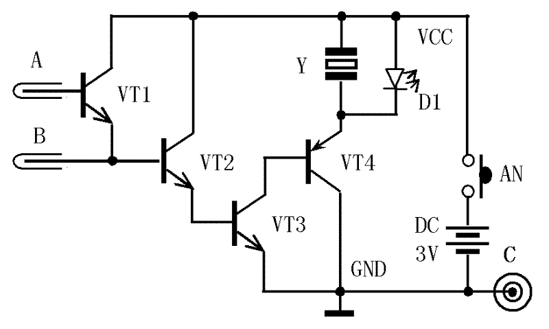
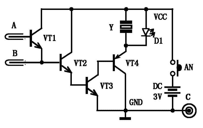
[0014] According to attached figure 1 The present invention can be realized by implementing the working principle diagram of the circuit shown and the description of the accompanying drawings and the technical requirements described below.
[0015] Component selection and its technical parameters
[0016] 1. The models of the three NPN transistors VT1, VT2 and VT3 in the circuit are: 2SC9013;
[0017] 2. The model of PNP transistor VT4 is: 2SC9012, the β value of the four transistors in the circuit is required to be ≥ 150, the withstand voltage is required to be ≥ 60V, and the higher the withstand voltage is required, the better;
[0018] 3. Buzzer Y requires an internal electronic circuit, working voltage: 2.2 ~ 3.0V;
[0019] 4. The light emitting diode D1 is a red super bright diode.
[0020] Circuit fabrication and circuit debugging
[0021] According to attached figure 1 The working principle diagram of the circuit shown, check whether the welding of all components i...
PUM
 Abstract
Description
Claims
Application Information