Optical voltage sensor and self-calibration method for realizing sensor

A technology of optical voltage sensing and optical voltage, which is applied in the direction of voltage/current isolation and measurement using digital measurement technology, can solve the problems of poor measurement accuracy and temperature stability, and achieve the effect of solving poor temperature stability

Inactive Publication Date: 2012-05-02
HARBIN INST OF TECH
View PDF6 Cites 13 Cited by
  • Summary
  • Abstract
  • Description
  • Claims
  • Application Information

AI Technical Summary

Problems solved by technology

[0006] The purpose of the present invention is to solve the problem of poor temperature stability of the existing optical v

Method used


Image

  • Optical voltage sensor and self-calibration method for realizing sensor
  • Optical voltage sensor and self-calibration method for realizing sensor
  • Optical voltage sensor and self-calibration method for realizing sensor

Examples


specific Embodiment approach 1

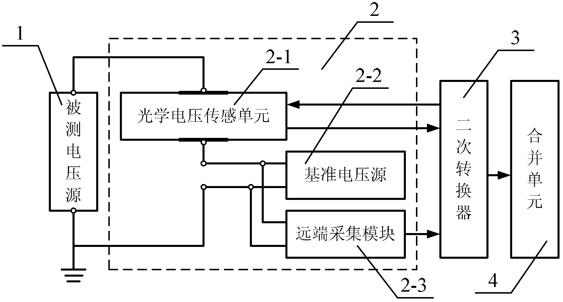
[0030] Specific implementation mode 1. Combination figure 1 Describe this specific embodiment, an optical voltage sensor, which includes an optical voltage sensing unit 2-1, a reference voltage source 2-2, and a remote acquisition module 2-3, and the upper electrode of the optical voltage sensing unit 2-1 is connected to A voltage signal input terminal to be measured of the optical voltage sensor 2, the input terminal is a non-ground terminal, and the ground terminal of the reference voltage source 2-2 is another voltage input terminal to be measured of the optical voltage sensor 2, and the input terminal is The ground terminal, the reference voltage signal output terminal of the reference voltage source 2-2 is connected to the lower electrode of the optical voltage sensing unit 2-1; the frequency of the voltage signal output by the reference voltage source 2-2 is greater than the frequency of the voltage signal to be measured; the remote The collection module 2-3 collects the...

specific Embodiment approach 2

[0031] Embodiment 2. Realize the self-calibration method of an optical voltage sensor described in Embodiment 1. A voltage signal input terminal of the optical voltage sensor 2 and a measured voltage source 1 output voltage signal U 1 The ground terminal of the reference voltage source 2-2 is connected to the ground terminal of the measured voltage source 1; the remote acquisition module 2-3 collects the output voltage signal U of the reference voltage source 2-2 2 , the remote acquisition module 2-3 converts the collected voltage signal into an optical pulse signal, and then transmits to the secondary converter 3 of the voltage transformer through an optical fiber; the secondary converter 3 of the voltage transformer sends The light source is transmitted to the light source input end of the optical voltage sensing unit 2-1 through an optical fiber, and the optical voltage sensing unit 2-1 simultaneously senses the voltage signal U 1 with U 2 , and transmit to the secondary c...


PUM


Abstract

The invention relates to a self-calibration method for realizing an optical voltage sensor, which relates to a self-calibration method for a sensor. A reference voltage source is designed to realize a self-calibration function of the optical voltage sensor. By using the current optical voltage sensor, measurement precision and temperature stability are low. By using the optical voltage sensor of the invention, the above problem can be solved. In the invention, a discrete Fourier algorithm is used to acquire an effective value of a voltage signal. Through adding a calculation sample number and windowing processing, influence of frequency fluctuation on effective value calculation can be reduced and the stability of a self-calibration coefficient can be increased. An optical voltage sensor measurement result is affected by a temperature. By using an optical current sensor in the invention, the above problem can be solved. Through testing, the measurement precision reaches an IEC 0.2 grade measuring requirement in a temperature scope of minus 40-60 DEG C. The sensor and the method are suitable for designing a voltage transformer.

Description

technical field [0001] The invention relates to an optical voltage sensor and a self-calibration method for realizing the sensor. Background technique [0002] Voltage transformer is an important equipment for voltage measurement in power system, and its measurement accuracy and operation reliability are closely related to the safe, reliable and economical operation of power system. The voltage transformers currently used mainly include electromagnetic voltage transformers, capacitive voltage divider voltage transformers and electronic voltage transformers. With the development of smart grids, electronic voltage transformers have received more and more attention and applications. The optical voltage transformer adopts the principle of Pockels electro-optic effect. It has no frequency band measurement limit, can accurately reflect the full voltage information including non-periodic components, and is the most ideal electronic voltage transformer. It is the development of ele...

Claims


Application Information

Patent Timeline
IPC IPC(8): G01R19/25G01R15/24
Inventor 郭志忠张国庆于文斌路忠峰申岩王贵忠
Owner HARBIN INST OF TECH
Why Eureka
Try Eureka