Self-calibration method for optical voltage sensor
A technology of optical voltage sensing and optical voltage, which is applied in the direction of voltage/current isolation and measurement using digital measurement technology, can solve the problems of poor measurement accuracy and temperature stability of optical voltage sensors, and achieve the effect of solving poor temperature stability
- Summary
- Abstract
- Description
- Claims
- Application Information
AI Technical Summary
Problems solved by technology
Method used
Image
Examples
specific Embodiment approach 1
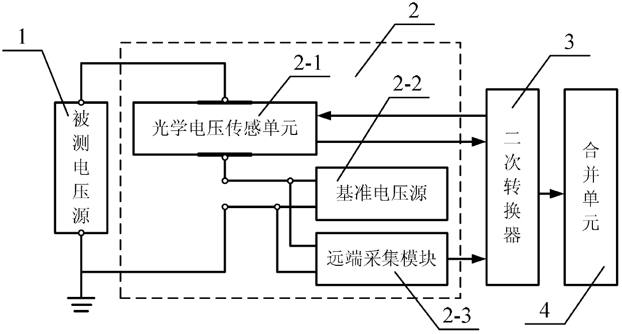
[0030] Specific implementation mode 1. Combination figure 1 Describe this specific embodiment, an optical voltage sensor, which includes an optical voltage sensing unit 2-1, a reference voltage source 2-2, and a remote acquisition module 2-3, and the upper electrode of the optical voltage sensing unit 2-1 is connected to A voltage signal input terminal to be measured of the optical voltage sensor 2, the input terminal is a non-ground terminal, and the ground terminal of the reference voltage source 2-2 is another voltage input terminal to be measured of the optical voltage sensor 2, and the input terminal is The ground terminal, the reference voltage signal output terminal of the reference voltage source 2-2 is connected to the lower electrode of the optical voltage sensing unit 2-1; the frequency of the voltage signal output by the reference voltage source 2-2 is greater than the frequency of the voltage signal to be measured; the remote The collection module 2-3 collects the...
specific Embodiment approach 2
[0031] Embodiment 2. Realize the self-calibration method of an optical voltage sensor described in Embodiment 1. A voltage signal input terminal of the optical voltage sensor 2 and a measured voltage source 1 output voltage signal U 1 The ground terminal of the reference voltage source 2-2 is connected to the ground terminal of the measured voltage source 1; the remote acquisition module 2-3 collects the output voltage signal U of the reference voltage source 2-2 2 , the remote acquisition module 2-3 converts the collected voltage signal into an optical pulse signal, and then transmits to the secondary converter 3 of the voltage transformer through an optical fiber; the secondary converter 3 of the voltage transformer sends The light source is transmitted to the light source input end of the optical voltage sensing unit 2-1 through an optical fiber, and the optical voltage sensing unit 2-1 simultaneously senses the voltage signal U 1 with U 2 , and transmit to the secondary c...
PUM
 Abstract
Description
Claims
Application Information
 - R&D
- Intellectual Property
- Life Sciences
- Materials
- Tech Scout
- Unparalleled Data Quality
- Higher Quality Content
- 60% Fewer Hallucinations
Browse by: Latest US Patents, China's latest patents, Technical Efficacy Thesaurus, Application Domain, Technology Topic, Popular Technical Reports.
© 2025 PatSnap. All rights reserved.Legal|Privacy policy|Modern Slavery Act Transparency Statement|Sitemap|About US| Contact US: help@patsnap.com


