Current sensor capacitance measurement circuit

A current sensor and capacitance measurement technology, which is applied in the direction of measuring electrical variables, measuring resistance/reactance/impedance, measuring devices, etc., can solve problems that are difficult to completely eliminate, complex circuit structure, high cost, etc., to solve the charge injection effect and improve measurement The effect of precision and good resolution

Inactive Publication Date: 2012-05-02
常熟市董浜镇华进电器厂
View PDF5 Cites 13 Cited by
  • Summary
  • Abstract
  • Description
  • Claims
  • Application Information

AI Technical Summary

Problems solved by technology

However, due to the pulsating noise in the continuous charge and discharge measurement signal, it needs to be filtered to remove the pulsating component, but the introduction of the filter has become a bottleneck to improve the data acquisition speed
In addition, the charge transfer method uses the electronic switch network to control the charging and discharging of the circuit, and the influence of the charge injection effect of the electronic switch on the measurement results is difficult to completely eliminate; the AC method needs to consider phase compensation, the circuit structure is complex, and the cost is also high.

Method used


Image

  • Current sensor capacitance measurement circuit
  • Current sensor capacitance measurement circuit
  • Current sensor capacitance measurement circuit

Examples


Embodiment Construction

[0014] The preferred embodiments of the present invention will be described in detail below with reference to the accompanying drawings, so that the advantages and features of the present invention can be more easily understood by those skilled in the art, so as to make a clearer and clearer definition of the protection scope of the present invention.

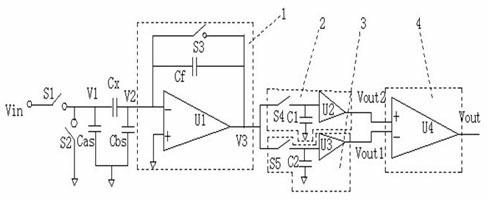
[0015] See figure 1 The embodiment of the present invention includes: a switch S1, a switch S2, a capacitor Cx, a charge amplification circuit 1, a sample holder 2, a sample holder 3, and an instrumentation amplifier 4. One end of the switch S1 is connected to the excitation voltage source, the other end is connected to the capacitor Cx and connected to the ground in parallel with the switch S2. The left and right plates of the capacitor Cx are respectively connected to the capacitor Cas and the capacitor Cbs, and the capacitor Cas and the capacitor Cbs are connected in parallel to the ground, and the capacitor Cas And the capacita...


PUM


Abstract

The invention discloses a current sensor capacitance measurement circuit which comprises a first switch, a second switch, a first capacitor, a charge amplification circuit, a first sampling retainer, a second sampling retainer and an instrument amplifier. The charge amplification circuit comprises a first operational amplifier, a second capacitor and a third switch. The first switch and the second switch are in parallel connection at a left side terminal of the first capacitor. The first sampling retainer and the second sampling retainer are in parallel connection, one end of the two retainers is connected with the charge amplification circuit, and the other end of the two retainers is connected with the instrument amplifier. Control sequences of the first switch, the second switch and the third switch are different. Through the above mode, data acquisition speed of a data acquisition system can be greatly raised, influence of a charge injection effect of an electronic switch on measurement precision is solved well, and the current sensor capacitance measurement circuit has the advantages of high resolution, simple circuit structure and low cost.

Description

Technical field [0001] The invention relates to a current sensor capacitance measuring circuit, in particular to a current sensor capacitance measuring circuit that solves the charge injection effect of an electronic switch. Background technique [0002] Capacitance sensors are widely used in a variety of detection systems to measure physical quantities such as injection level, pressure, displacement, and acceleration. In some occasions, such as electrical capacitance tomography systems, the change in sensing capacitance is as small as fF, which places higher requirements on capacitance measurement circuits. [0003] At present, the main methods used to solve the measurement of weak capacitance are the charge transfer method and the AC method. The basic measurement principle of these two circuits is to continuously charge and discharge the measured capacitance through the excitation signal to form a current or voltage signal proportional to the measured capacitance, thereby measur...

Claims


Application Information

Patent Timeline
Patent Type & Authority Applications(China)
IPC IPC(8): G01R27/26
Inventor 马进
Owner 常熟市董浜镇华进电器厂
Why Eureka
Try Eureka