Pneumatic double-plate optical fiber tester for LED (Light Emitting Diode) indicating lamp

A technology of LED indicator light and tester, which is applied in the direction of lamp testing, instrumentation, measuring electricity, etc., can solve the problems of high manpower consumption, high cost, cumbersome test operation process, etc., to improve production efficiency, simplify operation procedures, and improve test efficiency. efficiency effect

Active Publication Date: 2012-05-02
TIANJIN ZHONGHUAN ELECTRONICS COMP
View PDF9 Cites 12 Cited by
  • Summary
  • Abstract
  • Description
  • Claims
  • Application Information

AI Technical Summary

Problems solved by technology

[0002] At present, LED indicator light testing problems are often encountered in the implementation of automotive dashboard control panel industrialization system engineering. Currently, LED testing instruments on the market include general-purpose AC power supplies, power meters, digital multimeters, etc. Such testing instruments are usually suitable for small Batch product inspection and use, the test operation process is cumbersome and labor-intensive. There is no ready-made special test instrument for this type of product in China. There are instruments with similar functions abroad, but they are customized and expensive. Therefore, LED indicator light testers have become It is a bottleneck that restricts the industrialization of automotive dashboard control panels. Therefore, the development of testing instruments for this product is of great significance for improving the testing efficiency of LEDs, improving product quality, simplifying operating procedures and improving production efficiency. At present, domestic counterparts have no such The LED indicator light tester appears, and there is no report on this technical article in the literature

Method used


Image

  • Pneumatic double-plate optical fiber tester for LED (Light Emitting Diode) indicating lamp
  • Pneumatic double-plate optical fiber tester for LED (Light Emitting Diode) indicating lamp
  • Pneumatic double-plate optical fiber tester for LED (Light Emitting Diode) indicating lamp

Examples


Embodiment Construction

[0019] In order to understand the present invention more clearly, describe the present invention in detail in conjunction with accompanying drawing and embodiment:

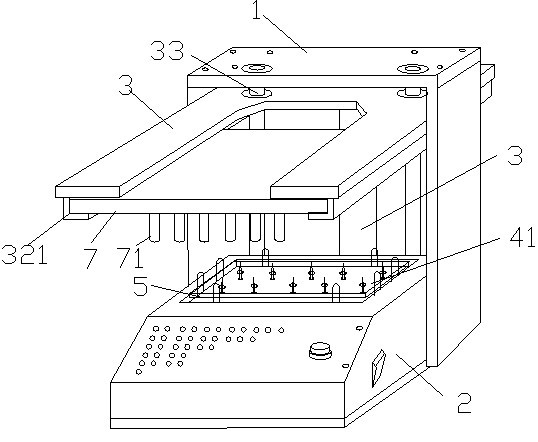
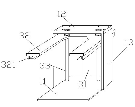
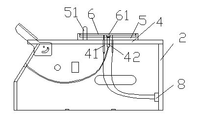
[0020] Such as Figure 1 to Figure 5 As shown, a pneumatic double-plate optical fiber LED indicator light tester includes a test console and a test circuit. The test console is composed of a support 1, a control box 2 and a pneumatic device 3; the support 1 is composed of a base plate 11, an upper cover plate 12 and The side plate 13 is formed; with the bracket 1 as the support body, the control box 2 is fixed on the bottom plate 11 of the bracket 1; the inner side of the control box 2 is provided with a test needle bed 4, and the upper part of the test needle bed 4 is the positioning of the circuit board (PCB) plate 5, the positioning plate 5 is inlaid on the opening on the top of the box body, the surface of the positioning plate 5 has a structure through hole and a positioning column 51, the positioning pla...


PUM


Abstract

The invention relates to a pneumatic double-plate optical fiber tester for an LED (Light Emitting Diode) indicating lamp. A test operation board comprises a bracket, a control box and a pneumatic device; the bracket is taken as a support body; a test needle bed is arranged at the inner side of the control box; a positioning board for a circuit board is arranged above the test needle bed and is embedded in an open pore at the upper part of a box body; the pneumatic device comprises an air cylinder, a lifting stand and guide posts; the lifting stand is driven by the air cylinder to downwards move and press the circuit board, so that LED test points on the back of the circuit board are in contact with test needle heads; glass light posts are in contact with the LED surface of the circuit board; during testing, a power supply of a test circuit is connected and the LED is lightened; light transmits to a tester panel window of the test operation board through the glass light posts and optical fibers; and whether the LED is qualified or not is judged by visually observing the luminous state of the LED; and according to the test instrument, test efficiency of the LED can be increased, quality of products can be improved, operation work procedures are simplified and production efficiency can be increased.

Description

technical field [0001] The invention relates to a test instrument, in particular to a pneumatic double-plate optical fiber LED indicator light tester. Background technique [0002] At present, LED indicator light testing problems are often encountered in the implementation of automotive dashboard control panel industrialization system engineering. Currently, LED testing instruments on the market include general-purpose AC power supplies, power meters, digital multimeters, etc. Such testing instruments are usually suitable for small Batch product inspection and use, the test operation process is cumbersome and labor-intensive. There is no ready-made special test instrument for this type of product in China. There are instruments with similar functions abroad, but they are customized and expensive. Therefore, LED indicator light testers have become It is a bottleneck that restricts the industrialization of automotive dashboard control panels. Therefore, the development...

Claims


Application Information

Patent Timeline
Patent Type & Authority Applications(China)
IPC IPC(8): G01R31/44G01R31/01
Inventor 吴涛王克伟高长泽马利孟辉
Owner TIANJIN ZHONGHUAN ELECTRONICS COMP
Why Eureka
Try Eureka