Integrated structure of rigidized inflatable deployable truss type planar antenna and solar array

A technology that integrates a plane antenna and a windsurfing board. It is applied in the directions of folded antennas, antenna supports/installation devices, electrical components, etc., and can solve the problems of decreased signal accuracy of plane antennas, decreased structural rigidity and fundamental frequency, and difficulty in aircraft attitude control. Achieve high deployment reliability, improve anti-vibration capability, and improve signal accuracy and sensitivity.

Active Publication Date: 2014-02-12
北京捭阖经纬创新科技有限公司
View PDF4 Cites 0 Cited by
  • Summary
  • Abstract
  • Description
  • Claims
  • Application Information

AI Technical Summary

Problems solved by technology

[0006] The purpose of the present invention is to solve the problem of complex structure, easy failure, poor deployment reliability, heavy overall weight, low folding efficiency, and poor emission of existing mechanical unfolded solar panels and existing mechanical unfolded planar antennas in single use. The problem of large volume and high cost; at the same time, it solves the problem that the structural stiffness and fundamental frequency decrease with the increase of the structure size due to the large-area planar frame type expansion structure, which is easy to cause resonance with the main body of the aircraft and makes it difficult to control the attitude of the aircraft, and leads to The problem of the decrease in signal accuracy of planar antennas, and then provide a rigid inflatable unfolding truss-type planar antenna and solar panel integrated mechanism

Method used


Image

  • Integrated structure of rigidized inflatable deployable truss type planar antenna and solar array
  • Integrated structure of rigidized inflatable deployable truss type planar antenna and solar array
  • Integrated structure of rigidized inflatable deployable truss type planar antenna and solar array

Examples


specific Embodiment approach 1

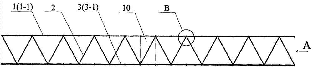
[0024] Specific implementation mode one: see figure 1 , Figure 4 with Figure 8 , the present embodiment includes: a solar panel support 1, a support tube 2, a planar antenna support 3, a planar antenna module 4, a solar panel substrate 8, a solar battery sheet 9, and a satellite or a space station 10, a solar panel support 1 and a planar antenna The support pipes 2 are connected between the brackets 3 to form a quadrilateral truss structure, the solar panel substrate 8 is arranged on the truss structure, the solar cells 9 are fixed on the solar panel substrate 8, and the planar antenna module 4 is arranged on the truss structure. The lower part of the structure forms a planar antenna, and the satellite or space station 10 is arranged in the middle or end of the truss structure. After the present invention is sent into the space orbit and inflated, unfolded and stiffened, the solar panels face the sun and the planar antenna faces the ground.

specific Embodiment approach 2

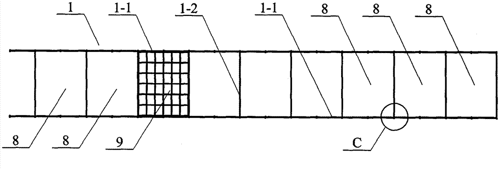
[0025] Specific implementation mode two: see figure 2 , the solar panel bracket 1 described in this embodiment includes: two sailboard longitudinal inflation pipes 1-1 and sailboard transverse inflation pipes 1-2, and a sailboard is connected between the two sailboard longitudinal inflation pipes 1-1 Horizontal inflatable pipe 1-2, sailboard longitudinal inflatable pipe 1-1 and sailboard horizontal inflatable pipe 1-2 are connected to each other, each is composed of sailboard longitudinal inflatable pipe 1-1 and sailboard horizontal inflatable pipe 1-2 A solar panel base plate 8 is arranged in the composed unit. Other components and connections are the same as those in the first embodiment.

specific Embodiment approach 3

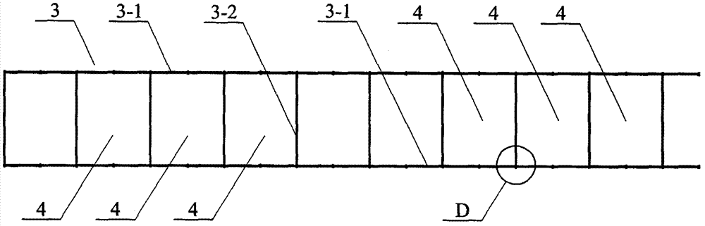
[0026] Specific implementation mode three: see image 3 , the planar antenna bracket 3 described in this embodiment includes: two antenna longitudinal air tubes 3-1 and antenna transverse air tubes 3-2, and an antenna horizontal air tube 3-2 is connected between the two antenna longitudinal air tubes 3-1 2. Antenna longitudinal inflatable tube 3-1 and antenna transverse inflatable tube 3-2 are connected to each other, and a planar antenna module is arranged in each unit composed of antenna longitudinal inflatable tube 3-1 and antenna transverse inflatable tube 3-2 4. Other components and connections are the same as those in the first embodiment.


PUM


Abstract

The invention provides an integrated structure of a rigidized inflatable deployable truss type planar antenna and a solar array. A substrate of the solar array provided by the invention is arranged at the upper side of a truss structure; a solar cell slice is fixed on the upper surface of the solar array; a planar antenna module is arranged at the lower side of the truss structure to form the planar antenna; and a satellite or a space station is arranged at the middle part or the end part of the truss structure. In the invention, a rigidized inflatable deployable truss is used as the main body of the integrated structure; the truss can be flexibly folded during launching, is high in folding efficiency, small in launching volume and convenient for the traditional launching technology and launching equipment to launch large-aperture antennae and large-area solar arrays; after the launched large-aperture antennae and large-area solar arrays enter tracks, the integrated structure is unfolded and rigidized, is higher in structural rigidity and fundamental vibrational frequency and is beneficial to the posture control and the stable running on tracks of aircrafts such as the satellite and the like, the remarkable improvement of anti-vibration performance of the planar antenna and the improvement of precision and sensitivity of signals.

Description

technical field [0001] The invention relates to an integrated structure of a truss-type planar antenna and a solar sail panel that can be rigidized and inflated. Background technique [0002] Planar antennas and solar panels (solar arrays or solar wings) have been widely used in satellites, manned spacecraft, space stations and other aircraft. Planar antennas are used for spaceborne synthetic aperture radar as signal transceiver components, and solar panels are used Space vehicles such as satellites are used as power supply components, but the planar antennas or solar panels used in the current aircraft are all in the form of mechanical unfolded structures, and are installed separately on the aircraft. [0003] Existing deployable solar panels mainly adopt a mechanical unfolding support structure, which is composed of many rigid components connected through a connecting mechanism, a control unfolding mechanism and a locking mechanism, which has complex structures and is pron...

Claims


Application Information

Patent Timeline
Patent Type & Authority Patents(China)
IPC IPC(8): H01Q1/08H01Q1/22H02S20/00B64G1/44H01L31/042
CPCY02E10/50
Inventor 苗常青王友善刘畅田爽谭惠丰杜星文
Owner 北京捭阖经纬创新科技有限公司
Why Eureka
Try Eureka