Power factor correcting and converting method and device for eliminating power frequency ripple waves by peak load shifting

A power factor correction and peak-shaving and valley-filling technology, which is applied in the direction of output power conversion devices, high-efficiency power electronic conversion, electrical components, etc., can solve problems such as small bandwidth and poor dynamic performance, so as to improve efficiency, reduce costs, and improve The effect of dynamic performance

Inactive Publication Date: 2012-05-02
SOUTHWEST JIAOTONG UNIV
View PDF5 Cites 20 Cited by
  • Summary
  • Abstract
  • Description
  • Claims
  • Application Information

AI Technical Summary

Problems solved by technology

In traditional high power factor application circuits, the input current strictly tracks the input AC voltage, and the input power on the AC input side also changes, and its change frequency is twice the frequency of the AC input voltage. After p

Method used


Image

  • Power factor correcting and converting method and device for eliminating power frequency ripple waves by peak load shifting
  • Power factor correcting and converting method and device for eliminating power frequency ripple waves by peak load shifting
  • Power factor correcting and converting method and device for eliminating power frequency ripple waves by peak load shifting

Examples


Embodiment 1

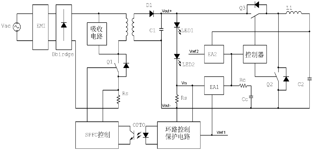
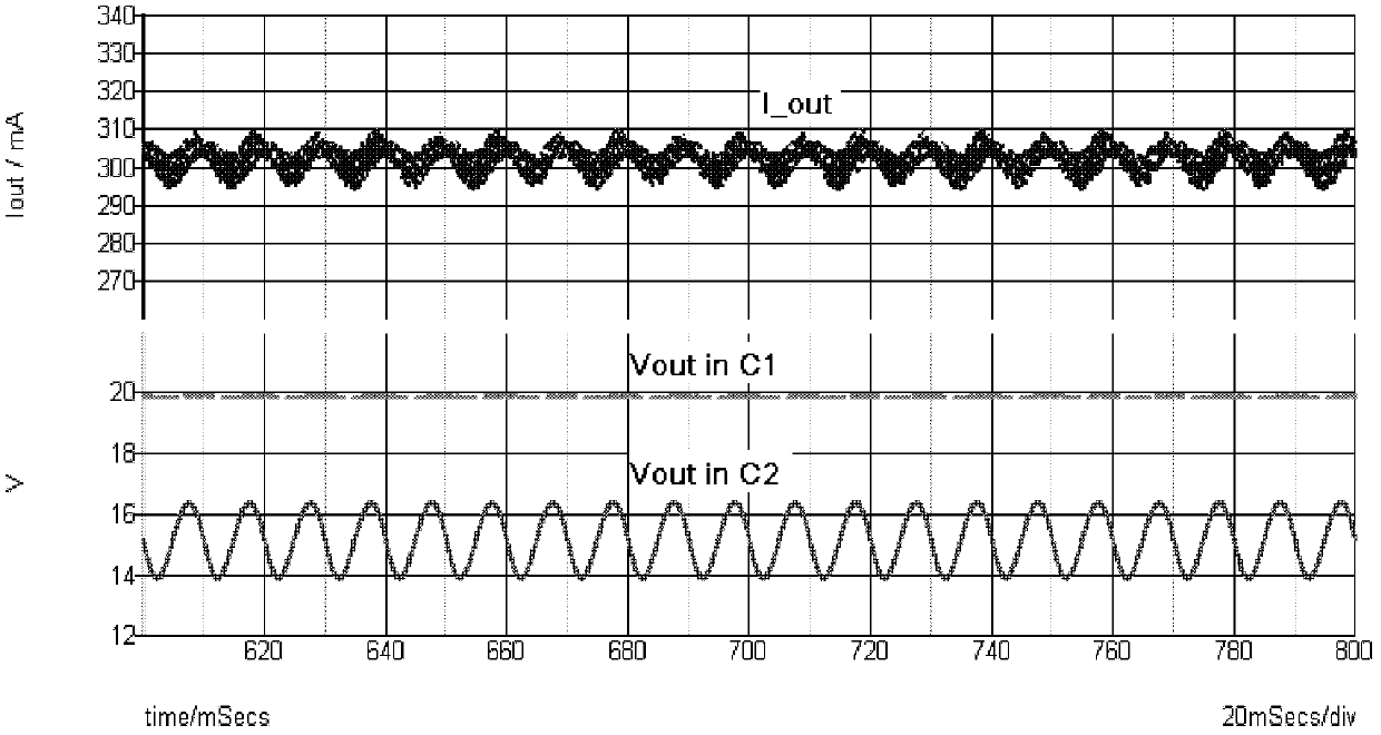
[0020] figure 2 It is shown that a specific embodiment of the present invention is a control method of a switching power supply, which adopts an isolated AC / DC constant current output conversion method, and its specific method is:

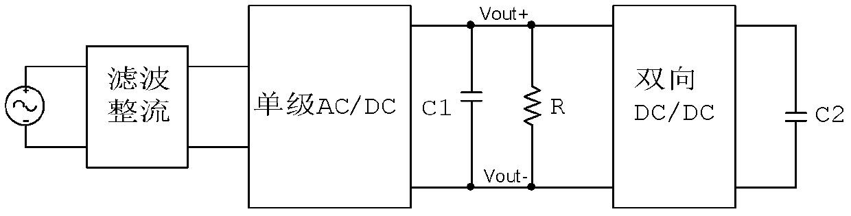
[0021] The AC input Vac passes through the EMI and the rectifier bridge Dbridge, and connects to the flyback circuit. Through a single-stage flyback converter with PFC function, the upper end of the DC output capacitor C1 is connected to the upper end of the LED string, the lower end of the LED string is connected to the current detection resistor RS, and the lower end of RS is connected to the lower end of C1. The DC output capacitor C1 of the single-phase flyback PFC converter is connected in parallel with the input end of the bidirectional Buck-Boost DC / DC converter with boost output, and the energy storage capacitor C2 is connected to the step-down output end of the bidirectional Buck-Boost DC / DC converter. Single-phase flyback PFC converter ...

Embodiment 2

[0023] Figure 5 It is shown that a specific embodiment of the present invention is a control method of a switching power supply, which adopts a non-isolated DC / AC constant voltage output conversion method, and its specific method is: the DC input E1 is connected to the inductance of the Boost boost circuit L1, consists of L1, Q1, Q2 to form a non-isolated boost circuit. Vref1 is a reference voltage relative to Vout-, and is used to set the DC voltage Vout+ on the front-stage capacitor C1 of the inverter. Vout+ and Vref1 generate a duty ratio control level signal through the error amplifier EA, and are modulated by the controller 1 to form pulse control signals of the switching tubes Q1 and Q2. The capacitor C1 is connected to the input terminal (step-down terminal) of the bidirectional DC / DC converter, and the output terminal of the bidirectional DC / DC converter is connected to the energy storage capacitor C2. Vout+ and Vref1 generate a duty cycle control level signal throu...


PUM


Abstract

The invention discloses a power factor correcting and converting method and device for eliminating power frequency ripple waves by peak load shifting. An extra bidirectional DC/DC (Direct Current/Direct Current) converter is combined with an AC/DC (Alternating Current/Direct Current) single-phase PFC (Power Factor Correction) converter; when an output of the single-phase PFC converter is higher than a reference voltage or a reference current, the bidirectional DC/DC converter is used for storing and absorbing surplus energy to an energy buffering and storing capacitor; when the output of the single-phase PFC converter is lower than the reference voltage or the reference current, the energy of the energy storage capacitor is released to a load; and alternating current ripple wave energy output by the single-phase PFC converter is compensated by the way so that double power frequency ripple waves on a filter at a direct current output end of the single-phase PFC converter are eliminated. According to the method and the device provided by the invention, a power frequency ripple wave voltage or a ripple wave current of a power factor correction converter is eliminated, and the following problems are solved: the cost is high due to utilizing a large-capacity capacitor to reduce the power frequency ripple waves of the power factor correction converter, the efficiency is low due to using a cascaded two-stage converter, and the like.

Description

technical field [0001] The invention relates to a method and device for eliminating power frequency ripple of a power factor correction converter, in particular to an AC / DC, isolation and non-isolation switching conversion method for eliminating power frequency ripple. Background technique [0002] In recent years, power electronics technology has developed rapidly, and power supply technology, which is an important part of the power electronics field, has gradually become a hot spot in application and research. As an indispensable part of various electronic equipment, the performance of the power supply is directly related to the safety and reliability of the entire system. With the advancement of power electronic device manufacturing technology and converter technology, switching power supply has established its mainstream position in the power supply field due to its advantages such as high efficiency and high power density. Most switching power supplies are connected to...

Claims


Application Information

Patent Timeline
IPC IPC(8): H02M1/42H02M1/14
CPCY02B70/126Y02B70/10
Inventor 许建平高建龙阎铁生张斐
Owner SOUTHWEST JIAOTONG UNIV
Why Eureka
Try Eureka