Diesel aftertreatment system

A technology for diesel and exhaust gas treatment, used in exhaust gas treatment, separation methods, machines/engines, etc., and can solve problems such as restricted oxidation catalysts

Inactive Publication Date: 2012-05-02
TENNECO AUTOMOTIVE OPERATING CO INC
View PDF2 Cites 11 Cited by
  • Summary
  • Abstract
  • Description
  • Claims
  • Application Information

AI Technical Summary

Problems solved by technology

However, such systems are limited at temperatures below 300°C and typically create a pressure drop across the oxidation catalyst, which must be accounted for when designing the rest of the system

Method used


Image

  • Diesel aftertreatment system
  • Diesel aftertreatment system
  • Diesel aftertreatment system

Examples


Embodiment Construction

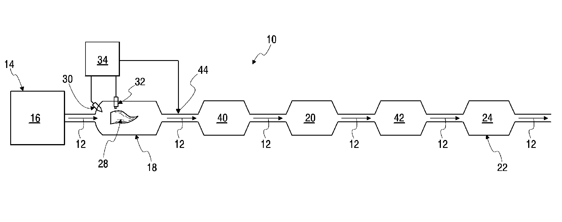
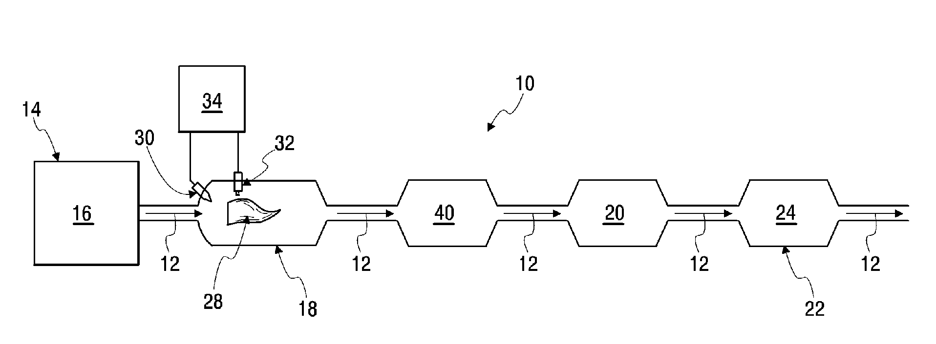
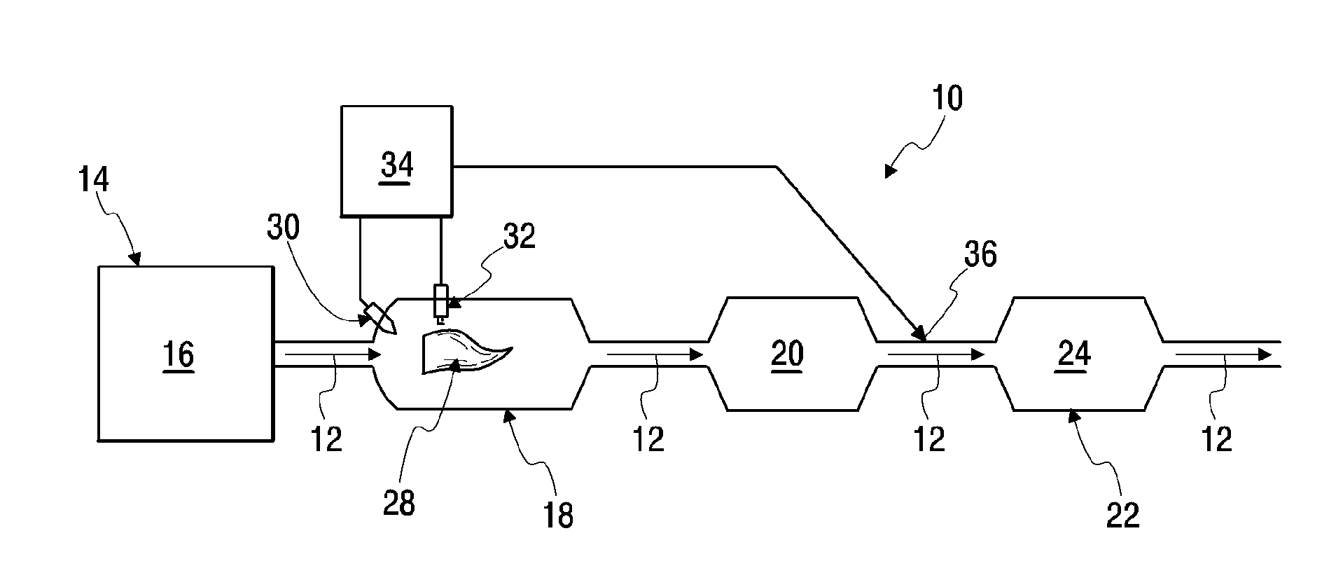
[0027] A diesel exhaust aftertreatment system 10 is provided to treat exhaust gas 12 from a diesel combustion process 14 , such as a diesel compression engine 16 . Exhaust gas 12 typically contains oxides of nitrogen (NO x ), such as nitrogen oxides (NO) and nitrogen dioxide (NO 2 ), particulate matter (PM), hydrocarbons, carbon monoxide (CO) and other combustion by-products.

[0028] The system 10 includes a combustor 18 that selectively supplies elevated temperature exhaust gas 12 to the remainder of the system 10; a diesel particulate filter (DPF) 20 connected downstream of the combustor 18 to receive exhaust gas therefrom. Gas 12; NOx reduction device 22, such as selective catalytic reduction catalyst (SCR) 24, such as figure 1 shown, or lean NO x trap 26, such as figure 2 As shown, it is connected downstream of DPF 20 to receive exhaust gas 12 therefrom. To overcome the low operating temperatures within the exhaust 12 of a lean-burn engine (e.g., a diesel compressio...


PUM


Abstract

A diesel exhaust gas aftertreatment system (10) is provided to treat the exhaust (12) from a diesel combustion process (14), such as a diesel compression engine (16). The system (10) includes a burner (18) that selectively supplies the exhaust (12) at an elevated temperature to the rest of the system (10), a diesel particulate filter (20) connected downstream from the burner (18) to receive the exhaust (12) therefrom, and a NOx reducing device (22) connected downstream from the filter (20) to receive the exhaust therefrom.

Description

[0001] Cross References to Related Applications [0002] Not applicable [0003] Federally funded research or development [0004] Not applicable [0005] Microfiche / Copyright Citation [0006] Not applicable. technical field [0007] The present invention relates to systems and methods for treating exhaust from a diesel combustion process, such as a diesel compression engine, and more particularly to reducing nitrogen oxides (NOx) from a diesel compression engine. x ) and particulate matter (PM) systems. Background technique [0008] Environmental regulations promote increased requirements to reduce NO from diesel combustion processes, especially from diesel compression engines. x and PM emission limits. While a Diesel Particulate Filter (DPF) can achieve the required PM (which is usually carbonaceous particles in the form of soot) reduction, it still needs to be able to provide NO x Improved system for reduction and reduction of particulate matter provided by DPF. ...

Claims


Application Information

Patent Timeline
Patent Type & Authority Applications(China)
IPC IPC(8): B01D53/56
CPCF01N2610/03F01N13/02F01N2240/14F01N3/106F01N3/025F01N3/0807F01N3/0842F01N3/035Y02T10/24F01N2610/04F01N3/0231F01N3/2066F01N2610/02F01N13/009Y02T10/12B01D53/56B01D53/86B01D53/92B01D53/94
Inventor A.J.科特尔巴T.E.杰克逊D.A.耶金A.冈多根T.加纳
Owner TENNECO AUTOMOTIVE OPERATING CO INC
Why Eureka
Try Eureka