Electronic mechanical brake and automobile

An electronic mechanical brake and brake disc technology, which is applied in the automotive field, can solve problems such as low accuracy of software adjustment devices, expensive corner sensors, and complex processing and assembly, and achieve good real-time braking, simple structure, and low cost. low effect

Active Publication Date: 2014-07-30
CHERY AUTOMOBILE CO LTD
View PDF6 Cites 0 Cited by
  • Summary
  • Abstract
  • Description
  • Claims
  • Application Information

AI Technical Summary

Problems solved by technology

The accuracy of the software adjustment device is not high, and its braking clearance is 3-5 times that of the traditional hydraulic brake. The braking clearance is large, the braking distance is long, the response time is long, and the braking real-time performance is poor; The hardware adjustment device accurately locates the reverse angle of the brake motor through the rotation angle sensor. Although the accuracy has been improved, the rotation angle sensor is expensive and expensive, and additional signal lines are required, which increases the complexity of processing and assembly.

Method used


Image

  • Electronic mechanical brake and automobile
  • Electronic mechanical brake and automobile
  • Electronic mechanical brake and automobile

Examples


Embodiment 1

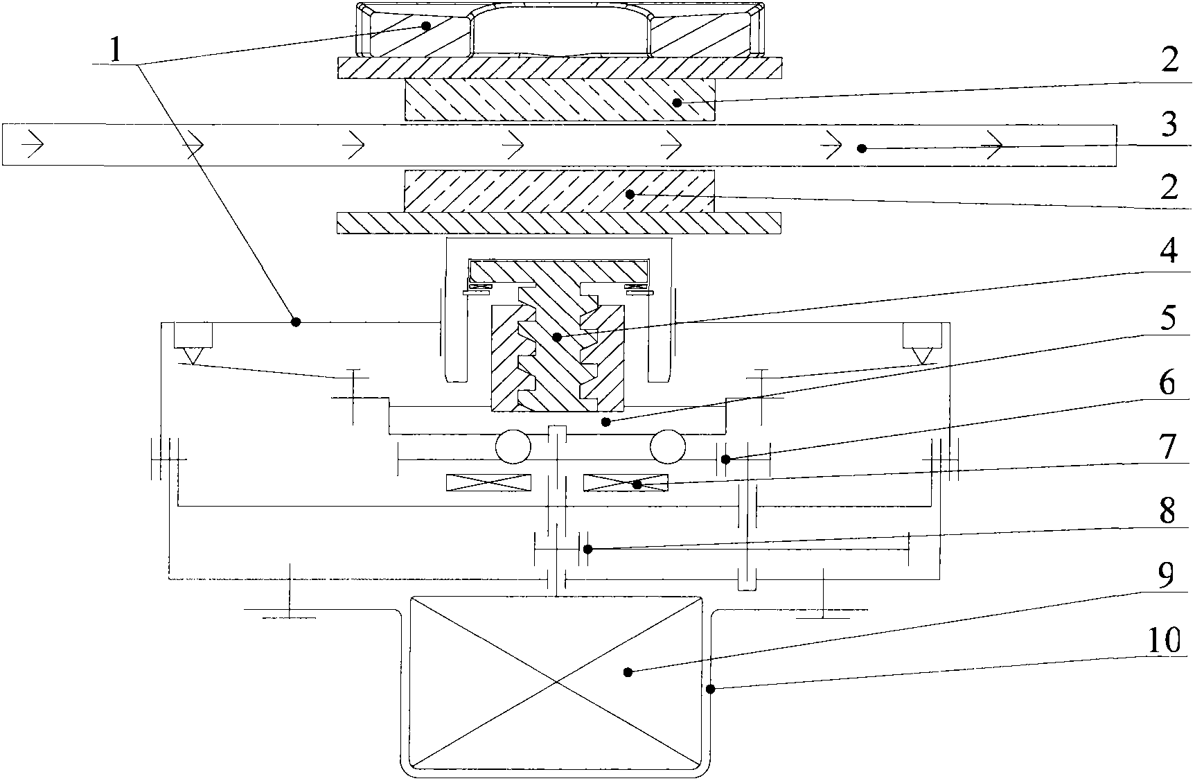
[0034] Such as figure 1 As shown, in this embodiment, the electromechanical brake includes a brake caliper body 1, a friction plate 2, a brake disc 3, a power mechanism that can push the friction plate 2 to move forward so as to clamp the brake disc 3, and can A gap self-adjusting device 4 for automatically adjusting the braking gap between the moving mechanism and the friction plate 2 , the gap self-adjusting device 4 is arranged between the moving mechanism and the friction plate 2 .

[0035] In this embodiment, the power mechanism includes a motor 9, a torque amplification mechanism, and a motion mechanism that converts the rotational motion of the motor 9 into an axial linear motion.

[0036] The torque amplification mechanism adopts a two-stage gear reduction mechanism, which includes a primary gear reduction mechanism 8 and a secondary gear reduction mechanism 6, the output shaft of the motor 9 is connected with the input end of the primary gear reduction mechanism 8, an...

Embodiment 2

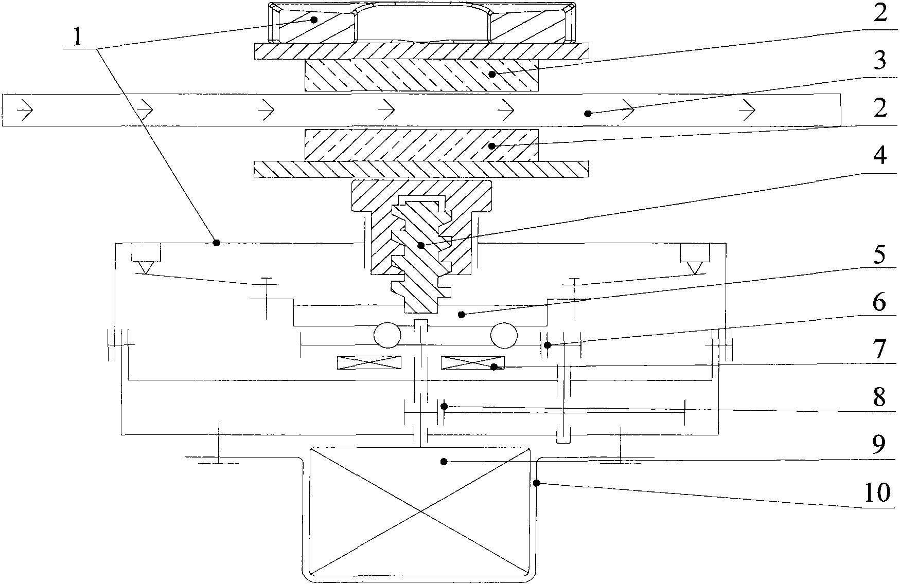
[0054] Such as image 3 As shown, the difference between this embodiment and Embodiment 1 is that the gap self-adjusting device in this embodiment is different from the gap self-adjusting device in Embodiment 1.

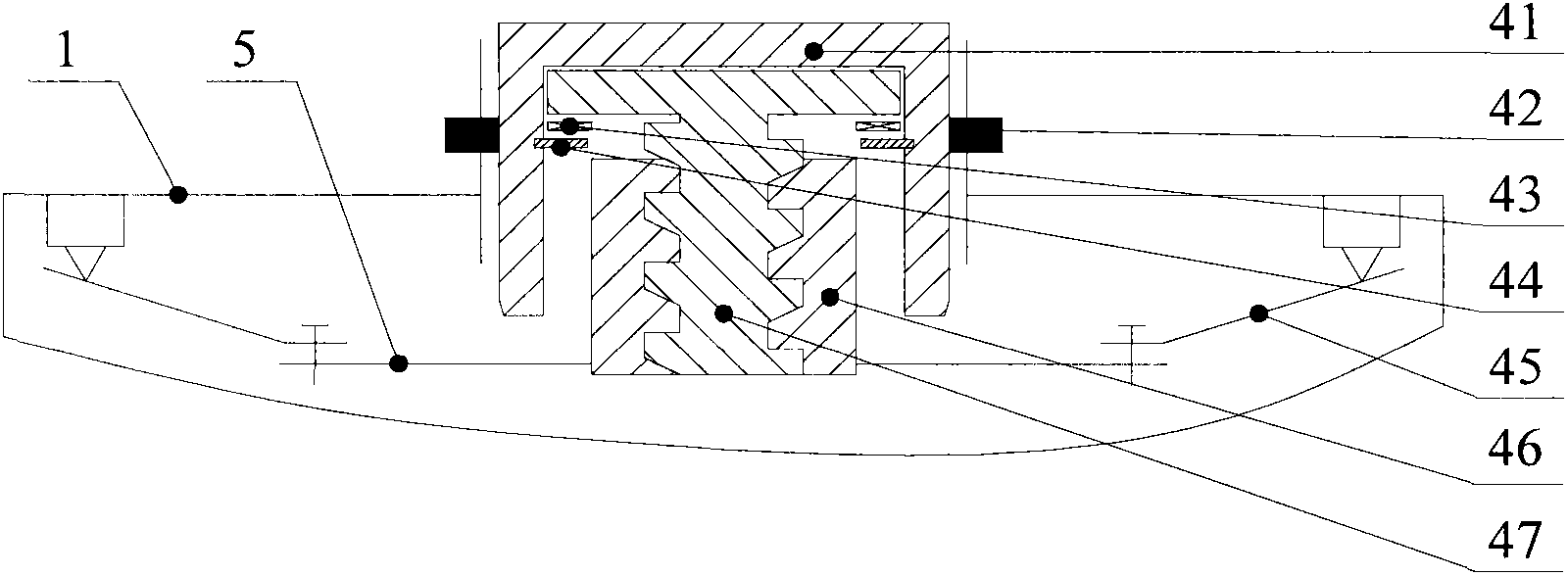
[0055] Such as Figure 4 As shown, in this embodiment, the gap self-adjusting device 4 includes a non-self-locking nut 46 , a non-self-locking bolt 47 , and a butterfly spring 45 .

[0056] Wherein, the feed unit includes non-self-locking bolts 47, and the non-self-locking bolts 47 are fixedly connected to the output end of the swash plate motion conversion mechanism 5, and the way of the fixed connection can be riveting or interference fit. , any other fixed connection method can also be adopted.

[0057] The compensation unit includes a non-self-locking nut 46 and a movement limiting mechanism. The non-self-locking nut 46 is sleeved on the non-self-locking bolt 47. The inner surface of the non-self-locking nut 46 is provided with a non-self-locking internal threa...


PUM


Abstract

The invention provides an electronic mechanical brake, which comprises a friction plate (2), a brake disc (3), a power mechanism and an automatic clearance regulating device (4). The power mechanism consists of a motor (9) and a movement mechanism connected with an output end of the motor (9), the automatic clearance regulating device is disposed between the movement mechanism and the friction plate and consists of a feeding unit and a compensation unit, the feeding unit is used for being driven by the movement mechanism to axially move, and the compensation unit is used for limiting rearward axial movement of the feeding unit so as to compensate a braking clearance after braking is completed. The invention correspondingly provides an automobile comprising the electronic mechanical brake. The electronic mechanical brake is simple in structure, suitable for assembly and manufacture, low in cost, short in braking distance, fast in response and fine in automatic clearance regulating effect.

Description

technical field [0001] The invention belongs to the technical field of automobile manufacturing, and in particular relates to an electromechanical brake and an automobile including the electromechanical brake. Background technique [0002] The electromechanical braking system was first used in aircraft, and is currently in the research and development period of transformation to the automotive field. The electromechanical braking system has the advantages of energy saving, environmental protection, good portability, easy integrated control, and superior braking performance, so it will become a mainstream development direction of the future vehicle braking system. [0003] In the electronic mechanical braking system, the gap self-adjusting device is generally used, and its purpose is to ensure the constancy of the braking response time of the vehicle. In the prior art, gap self-adjusting devices are generally divided into software adjusting devices and hardware adjusting dev...

Claims


Application Information

Patent Timeline
Patent Type & Authority Patents(China)
IPC IPC(8): B60T1/06B60L7/24
Inventor 高国兴周勇杜金枝王陆林
Owner CHERY AUTOMOBILE CO LTD
Why Eureka
Try Eureka