Eureka AIR delivers breakthrough ideas for toughest innovation challenges, trusted by R&D personnel around the world.

Electronic mechanical brake and automobile

An electromechanical brake and brake disc technology, applied in the automotive field, can solve the problems of high assembly size accuracy, complex brake assembly assembly, poor mechanical strength, etc., and achieve simple mechanism structure, good real-time braking, and easy The effect of manufacture

Active Publication Date: 2014-08-27
CHERY AUTOMOBILE CO LTD
View PDF6 Cites 0 Cited by
  • Summary
  • Abstract
  • Description
  • Claims
  • Application Information

AI Technical Summary

Problems solved by technology

[0005] The technical problem to be solved by the present invention is to provide an electromechanical brake and an automobile including the electromechanical brake in view of the above-mentioned deficiencies in the prior art. The electromechanical brake is small in size, simple in structure and easy to manufacture, solving the existing problems In the technology, the assembly of the brake assembly is complicated, the mechanical strength is poor, the assembly dimension accuracy is high, the manufacturing cost is high, and the volume is large.

Method used


Image

  • Electronic mechanical brake and automobile
  • Electronic mechanical brake and automobile
  • Electronic mechanical brake and automobile

Examples


Embodiment 1

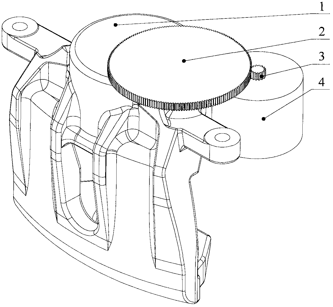
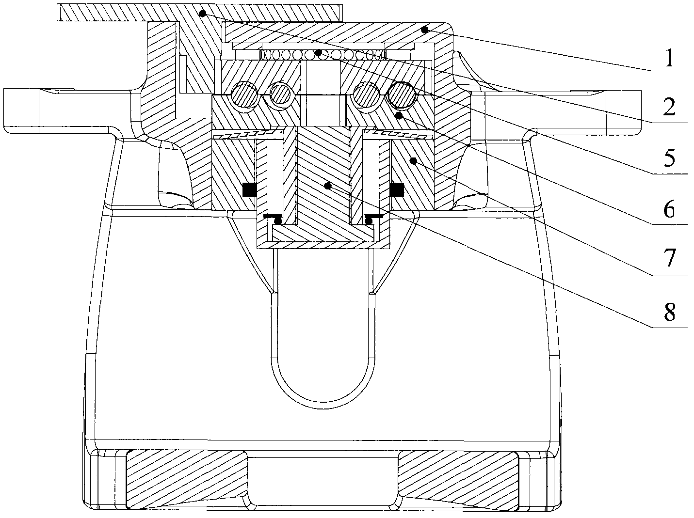
[0029] Such as figure 1 , 2 As shown, in this embodiment, the electromechanical brake includes a caliper body 1, a friction plate, a brake disc, a power mechanism that can push the friction plate to move forward to clamp the brake disc, and can automatically adjust the movement mechanism and the friction plate. The gap self-adjusting mechanism 8 of the braking gap between them, and the friction plates are arranged in front of the gap self-adjusting mechanism 8 .

[0030] Wherein, the power mechanism includes a motor 4, a reduction gear mechanism, and a motion mechanism that converts the rotary motion of the motor 4 into a linear motion; the reduction gear mechanism is located between the motor and the motion mechanism, and the input end of the reduction gear mechanism is connected to the The output shaft is connected, and its output end is connected with the movement mechanism. The reduction gear mechanism and the motor 4 are installed outside the caliper body 1, and the move...

Embodiment 2

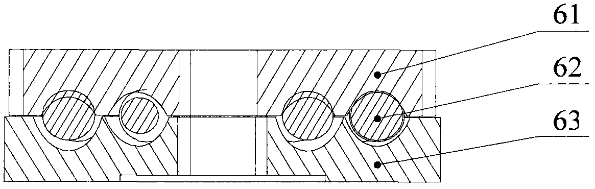
[0047] The difference between this embodiment and Embodiment 1 is that this embodiment does not have the gap self-adjusting mechanism 8 in Embodiment 1. Wherein, the front end of the lower swash plate 63 can be in direct contact with the friction plate, and the brake can be realized by eliminating the gap between the brake disc and the friction plate.

[0048] Other structures and uses in this embodiment are the same as those in Embodiment 1, and will not be repeated here.


PUM


Abstract

The invention provides an electronic mechanical brake, which comprises pliers, a brake disc, a friction plate and a power mechanism. The power mechanism consists of a motor, a movement mechanism and a reduction gear mechanism, rotational motion of the motor can be converted into linear motion by the aid of the movement mechanism, the friction plate is disposed at the front of the movement mechanism, the reduction gear mechanism is arranged between the motor and the movement mechanism, an input end of the reduction gear mechanism is connected with an output shaft of the motor, an output end of the reduction gear mechanism is connected with the movement mechanism, the motor and the reduction gear mechanism are disposed outside the pliers, and the movement mechanism is arranged inside the pliers and is a swash plate mechanism. The invention correspondingly provides an automobile comprising the brake. The electronic mechanical brake solves problems of complex assembly, poor mechanical strength, high requirement on assembly dimensional precision and manufacturing cost and large volume.

Description

technical field [0001] The invention belongs to the technical field of automobile manufacturing, and in particular relates to an electromechanical brake and an automobile including the electromechanical brake. Background technique [0002] With the development of automobile technology, people have put forward higher requirements for the power, economy, safety, maneuverability and comfort of automobiles, and more efficient and energy-saving electromechanical braking systems have emerged. Mechanical systems in automobiles There is a gradual transition to electromechanical systems. [0003] The electromechanical braking system uses electronic components to replace some mechanical components, and replaces all the brake pipelines with wires, which saves a lot of valve components in the braking system, shortens the braking response time, improves the braking performance, and saves In addition, the electronic control unit ECU is used to control the braking system as a whole, and e...

Claims


Application Information

Patent Timeline
Patent Type & Authority Patents(China)
IPC IPC(8): B60T1/06B60L7/24
Inventor 高国兴王陆林杜金枝
Owner CHERY AUTOMOBILE CO LTD
Why Eureka
Eureka Blog
Learn More