Track mounting structure

A technology of mounting structure and track, which is applied in the field of auto parts manufacturing, and can solve problems such as damage to glass rod blanks, difficulty in compression molding, and difficulty in accurately inserting glass rods into molds, etc.

Inactive Publication Date: 2012-05-09
WUXI DANGKOU TONGHE TEXTILE MACHINERY PLANT
View PDF0 Cites 2 Cited by
  • Summary
  • Abstract
  • Description
  • Claims
  • Application Information

AI Technical Summary

Problems solved by technology

[0002] In the automatic production line of circular automotive lamp glass blanks, the glass rods are conveyed to the molding machine by crawlers for compression molding. Due to the weight of the crawlers and the flexibility of the glass rods after heating, the mold position of the molding machine is too low. After heating The glass rod may not touch the mold of the molding machine, making it difficult to form the molding machine. The mold position of the molding machine is too high. Due to the weight of the track and the flexibility of the glass rod after heating, the glass rod after heating and the molding The blank is easy to collide with the molding machine, causing damage to the glass rod and the blank after molding, and it is difficult to accurately enter the mold after heating the glass rod

Method used


Image

  • Track mounting structure
  • Track mounting structure
  • Track mounting structure

Examples


Embodiment Construction

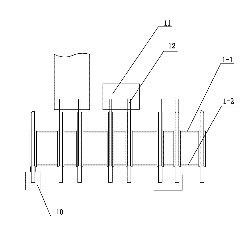
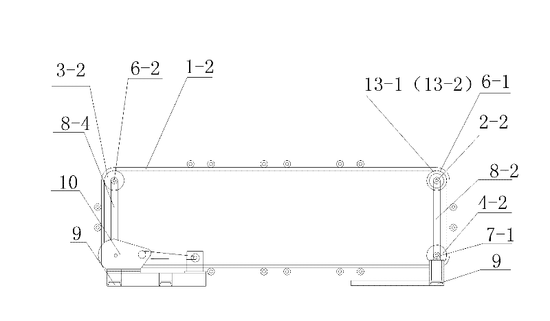
[0010] See figure 1 , figure 2 , image 3 , a crawler installation structure, which includes parallel double crawlers 1-1, 1-2, crawlers 1-1, 1-2 through the upper track wheels 2-1, 2-2, 3-1, 3- 2 and the lower track wheels 4-1, 4-2, 5-1, 5-2 support, the upper track wheels 2-1, 2-2 on one side are installed at both ends of the upper beam 6-1, and the upper track wheels on the other side The crawler wheels 3-1, 3-2 are installed on the two ends of the upper beam 6-2, and the upper beam 6-1, 6-2 is respectively supported by the support rods 8-1, 8-2, and the upper beam 6-1, 6- 2 are respectively supported by support rods 8-1, 8-2 and 8-3, 8-4, and the support rods 8-1, 8-2, 8-3, 8-4 are fixed on the base 9, and the upper one on one side Crawler wheels 2-1, 2-2 sides are provided with ratchet ratchet structures 13-1, 13-2, and the lower floor track wheels 4-1, 4-2 on one side are installed at the two ends of the lower crossbeam 7-1, and on the other side The lower track whe...


PUM


Abstract

The invention provides a track mounting structure, which can guarantee height difference of a track in stopping and rotating and the normal position of a heated glass bar placed on a molding press die, and enables the heated glass bar to enter the die accurately and easily. The track mounting structure comprises a track which is supported on a support through track wheels on two sides, and the track wheels are connected with a power transmission device. The track mounting structure is characterized in that a pawl-ratchet structure is arranged on the side of one of the two track wheels.

Description

technical field [0001] The invention relates to the technical field of auto parts manufacturing, in particular to a track installation structure. Background technique [0002] In the automatic production line of circular automotive lamp glass blanks, the glass rods are conveyed to the molding machine by crawlers for compression molding. Due to the weight of the crawlers and the flexibility of the glass rods after heating, the mold position of the molding machine is too low. After heating The glass rod may not touch the mold of the molding machine, making it difficult to form the molding machine. The mold position of the molding machine is too high. Due to the weight of the track and the flexibility of the glass rod after heating, the glass rod after heating and the molding The blank is easy to collide with the molding machine, causing damage to the glass rod and the molded blank, and it is difficult to accurately enter the mold after heating the glass rod. Contents of the ...

Claims


Application Information

Patent Timeline
Patent Type & Authority Applications(China)
IPC IPC(8): B65G15/00B65G21/00B65G23/06
Inventor 钱晓峰钱关林
Owner WUXI DANGKOU TONGHE TEXTILE MACHINERY PLANT
Why Eureka
Try Eureka