3D concrete printing path planning method for realizing inclined top surface

A printing path and 3D printing technology, applied in geometric CAD, instruments, manufacturing tools, etc., can solve the problems of drastic changes in the position of the printing line, separation, and overhanging the upper and lower printing materials, so as to improve accuracy and stability. Solve material accumulation and reduce the effect of complicated processes

Pending Publication Date: 2022-08-05
无锡荷清数字建筑科技有限公司
View PDF1 Cites 0 Cited by
  • Summary
  • Abstract
  • Description
  • Claims
  • Application Information

AI Technical Summary

Problems solved by technology

However, with the increasing demand for concrete shapes in the construction field, the horizontal layer-by-layer printing method has been unable to meet the forming requirements of all concrete shapes.
[0003] The horizontal layer-by-layer printing method can realize the shape printing with a relatively gentle top surface, but it cannot handle the concrete shape with a large top slope
This is because after the slope is layered horizontally, the layered "jaggies" will be exposed on the top surface, resulting in a poor overall effect
At the same time, for a slope with a large inclination, horizontal layering will cause the position of each layer of printing line to change drastically when it cuts the slope, and the upper and lower layers of printing materials will overhang or even completely separate.

Method used


Image

  • 3D concrete printing path planning method for realizing inclined top surface
  • 3D concrete printing path planning method for realizing inclined top surface
  • 3D concrete printing path planning method for realizing inclined top surface

Examples


Embodiment 1

[0077] Example 1: Illustration of a case of adding a mezzanine between adjacent variable planes

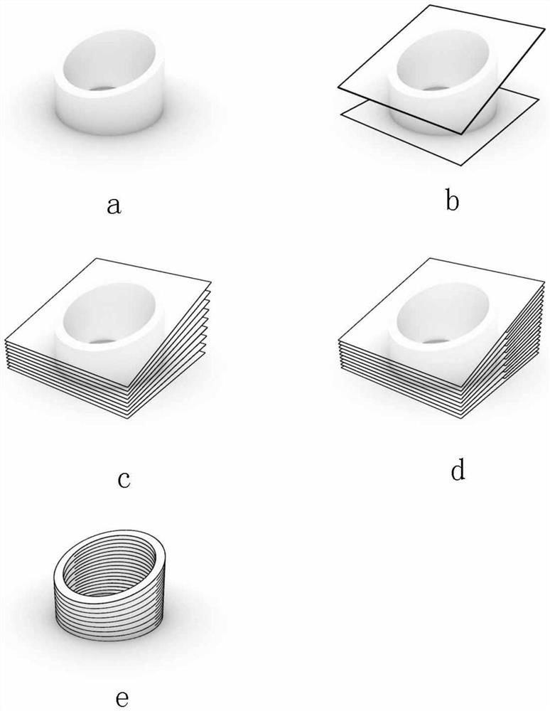
[0078] see attached figure 2 , this embodiment is a cylindrical concrete flowerpot with a sloped top, its model structure is relatively simple, and the ratio of the highest point elevation to the lowest point elevation on the top surface is 2:1, so a sandwich can be added between adjacent variable planes To achieve the printing path generation of the flowerpot, figure 2 a- figure 2e shows the layering process of the flower pot model. The steps of generating the path can be implemented according to the above-described process, wherein a takes the value of 2, and k takes the value of 1.

[0079] figure 2 a shows the overall shape of the first embodiment, figure 2 b shows the top and bottom planes of the extracted 3D model, figure 2 c shows a whole-layer variable-planar slice that generates a uniform change between the top and bottom planes, figure 2 d shows the inserti...

Embodiment 2

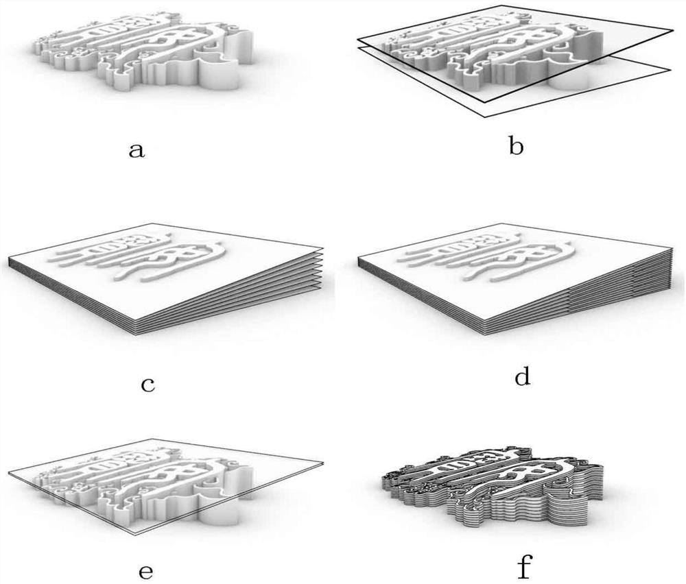
[0080] Example 2: Illustration of a case where two interlayers are added between adjacent variable planes

[0081] see attached image 3 , the slope of this embodiment is gentle, but the overall height of the model is very low, so the ratio of the highest point to the lowest point at the top still reaches 3:1. In addition, the text part of the topmost surface of the model is a separate protruding structure, Therefore, in this embodiment, the top surface of the pattern portion is considered as the top surface of the variable plane slice, see image 3 b, and the text part is sliced ​​with a plane parallel to the top surface of the pattern, see image 3 e shown. That is to say, a step needs to be added between steps 8 and 9, and the top plane of the pattern part is translated n times up along the Z-axis direction, n=int(H top / m), the distance is H top / n, where H top is the height of the text protruding in the Z-axis direction, m is the plane offset distance calculated in s...

Embodiment 3

[0083] Example 3: Example of adding three interlayers between adjacent variable planes

[0084] see attached Figure 4 , the characteristics of this embodiment are that the slope of the top surface is relatively large, the ratio of the elevation of the highest point to the lowest point reaches 4:1, and the side of the body is an arc. The way the model is cut does not evenly divide the sides of this arc. Therefore, in this embodiment, it is not only necessary to add three sets of interlayers between the whole layer and the plane, but also to change the way of defining the segmentation range in step 6 . Specifically, step 6 will be adjusted to: retain the method of determining the slicing line in step 6-1, but in step 6-2, instead of using the Z-axis direction to cut the model, let each slicing line Sweep along the trajectory of the arc on the side of the model to cut the model, such as Figure 4 As shown in d, this segmentation method can ensure that the planes within each t...


PUM


Abstract

The invention provides a 3D concrete printing path planning method for realizing an inclined top surface. The 3D concrete printing path planning method comprises the following steps: constructing a 3D digital model for 3D printing of a concrete building component; performing equal-interval gradient segmentation between the top surface and the bottom surface of the three-dimensional digital model to obtain a gradient whole-layer variable plane of the whole three-dimensional digital model; the three-dimensional digital model is vertically divided along the Z axis, k + 2 segmentation lines are obtained, and each whole-layer variable plane is divided into k + 1 ranges by the segmentation lines; adding a segmented interlayer between every two layers of whole-layer variable planes, wherein the interlayers are located in the k ranges close to one side of the highest point of the three-dimensional digital model; and taking a path obtained after primary segmentation and secondary segmentation as a 3D concrete printing path. According to the method, the conditions of infirm interlayer bonding and interlayer dislocation can be effectively avoided, meanwhile, the height distribution of each layer of concrete printing material in the 3D printing process is more reasonable, transition is more uniform, and the effect of a printed finished product is better.

Description

technical field [0001] The invention relates to the technical field of 3D printing concrete, in particular to a printing path planning method for 3D printing of complex concrete, and is specifically used to realize the planning of a 3D concrete printing path with an inclined top surface. Background technique [0002] The most commonly used printing path planning method in the field of 3D printing concrete is the contour processing process (US5529471A), that is, the horizontal layer-by-layer printing method, that is, the 3D model of the building is sliced ​​by the method of equidistant layering and transformed into a layer-by-layer printing path. , and then let the printing equipment (such as robotic arms, gantry printers) move along the printing path and evenly extrude the printing material through the pumping system, so as to realize the molding of concrete. However, with the increasing demand for concrete forms in the construction field, the horizontal layer-by-layer print...

Claims


Application Information

Patent Timeline
Patent Type & Authority Applications(China)
IPC IPC(8): B28B1/00B28B17/00B33Y10/00B33Y50/00B33Y50/02G06F30/13G06F30/20G06F113/10
CPCB28B1/001B28B17/0081B28B17/0072B33Y10/00B33Y50/00B33Y50/02G06F30/13G06F30/20G06F2113/10
Inventor 徐卫国
Owner 无锡荷清数字建筑科技有限公司
Why Eureka
Try Eureka