Method for detecting uniformity of powder injection molded feed

A powder injection molding and uniformity technology, which is applied in the direction of material analysis using measurement of secondary emissions, can solve the problem of lack of quantitative judgment basis and judgment, and achieve the effects of convenient operation, short time-consuming and simple process

Inactive Publication Date: 2014-01-01
CENT SOUTH UNIV
View PDF2 Cites 0 Cited by
  • Summary
  • Abstract
  • Description
  • Claims
  • Application Information

AI Technical Summary

Problems solved by technology

However, the uniformity of powder injection molding feed has not been tested by scanning electron microscopy. The reason is that the feed contains a large amount of binder, and the binder and powder are mixed with each other. If it does not pass statistical methods, It is difficult to judge it directly, lacking a quantitative judgment basis

Method used


Image

  • Method for detecting uniformity of powder injection molded feed
  • Method for detecting uniformity of powder injection molded feed
  • Method for detecting uniformity of powder injection molded feed

Examples


Embodiment 1

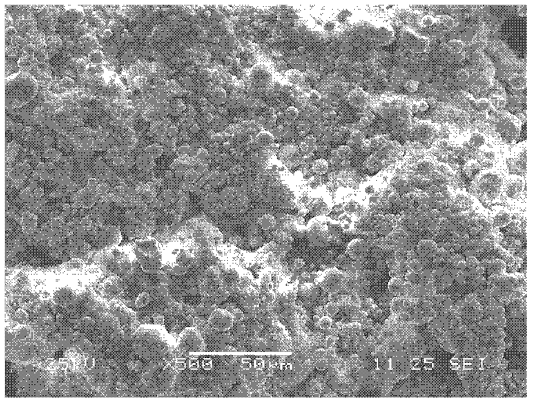
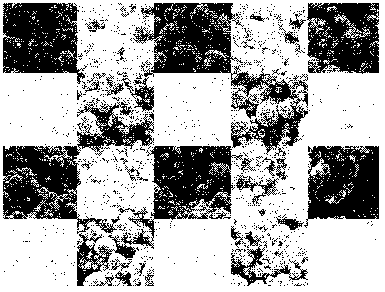
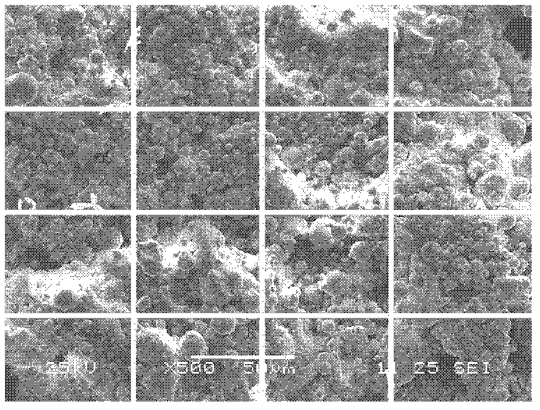
[0047] Choose 17-4PH stainless steel feed, the powder loading of the feed is 55% (volume percentage), the binder is 5% stearic acid, 35% paraffin, 25% polymethacrylate, 35% polyethylene, select Feed 0.5g at 2 different positions for sample preparation. Then put it into a scanning electron microscope for observation, and obtain pictures such as figure 1 with figure 2 shown. Divide it into 16 parts with the same area according to Table 1, such as image 3 with Figure 4 shown. Then use Image-Pro Plus software to count 16 regions. The results obtained in the order of Table 1 are as follows: the statistical results of position 1 electron microscope photos: 72.3%, 71.2%, 55.3%, 52.2%, 65.5%, 57.8%, 78.4%, 81.3%, 57.2%, 51.7%, 51.3%, 79.2%, 73.1%, 85.3%, 54.3%, 55.6%; Statistical results of position 2 electron microscope photos: 52.5%, 58.6%, 61.2%, 60.9%, 59.9%, 53.5%, 55.6%, 55.8%, 60.5%, 68.5%, 52.6%, 50.2%, 51.6%, 58.6%, 56.8%, 61.3%. The statistical results of the elec...

Embodiment 2

[0055] Select Ti-6A1-4V feeding material, binder system is stearic acid 10%, vegetable oil 25%, polymethacrylate 30%, polypropylene 35%, and the powder loading of feeding is 70% (volume percentage ), select 1g each of feed materials from 2 different positions, and prepare samples. Then put it into a scanning electron microscope for observation, and obtain pictures such as Figure 5 with Image 6 shown. Divide it into 16 parts with the same area according to Table 1, such as Figure 7 with Figure 8 shown. Then use Leica QWin software to count 16 regions. The results obtained are as follows: Statistical results of electron microscope photos at position 1: 76.3%, 65.2%, 59.3%, 61.2%, 69.4%, 74.6%, 71.3%, 66.8%, 81.5%, 83.5%, 90.2%, 52.1%, 73.4% , 79.3%, 66.3%, 73.6%; Statistical results of position 2 electron microscope photos: 78.5%, 72.6%, 83.4%, 86.5%, 56.6%, 75.2%, 78.6%, 65.3%, 88.5%, 75.8%, 64.7% , 75.9%, 81.6%, 78.3%, 74.1%, 76.7%. The statistical results of the e...

Embodiment 3

[0061] Choose 93W-4Ni-3Fe feed, the binder system is stearic acid 5%, polyethylene glycol 15%, polymethacrylate 40%, polyethylene 40%, and the powder loading of the feed is 60% (Volume percent), select 3 g of feeding materials in 3 different positions, and sample preparation. Then put it into a scanning electron microscope for observation. Divide it into 16 parts with the same area according to Table 1. The 16 regions were then counted using NIH Image software. The obtained results are as follows: Statistical results of position 1 electron microscope photos: 66.1%, 61.4%, 59.6%, 92.5%, 86.4%, 62.5%, 50.6%, 53.4%, 54.6%, 37.3%, 74.6%, 79.2%, 49.3% , 58.5%, 62.1%, 68.2%; the statistical results of position 2 electron microscope photos: 45.4%, 76.2%, 62.2%, 68.4%, 57.5%, 73.1%, 81.2%, 83.5%, 79.3%, 50.1%, 56.5% , 59.1%, 65.7%, 78.3%, 80.2%, 33.9%; the statistical results of position 3 electron microscope photos: 65.4%, 86.1%, 64.5%, 38.7%, 77.2%, 70.2%, 51.3%, 64.5%, 59.4% , ...


PUM


Abstract

The present invention discloses a method for detecting uniformity of a powder injection molded feed. The method comprises: selecting a material requiring detection; carrying out sampling for the material requiring detection; observing the sample by a scanning electron microscope (SEM); partitioning the obtained SEM pictures; adopting an image processing software to carry out statistics for the partitioned region; grouping the statistical results, and processing the grouped data to obtain the uniformity index. The method of the present invention has characteristics of simple process, convenient operation and short time consuming. With the method of the present invention, the uniformity of the powder injection molded feed can be high-precisionly and quantitatively detected on the microscopic state. The method is applicable for detection of the uniformity of the powder injection molded feed.

Description

technical field [0001] The invention discloses a method for detecting the uniformity of feeding materials for powder injection molding. Background technique [0002] Powder injection molding is an emerging near-net-shaping process developed on the basis of traditional powder metallurgy technology and creatively combining injection molding technology in the plastics industry. It has the advantages of conventional powder metallurgy and machining in the manufacture of high-quality precision parts. The incomparable advantages of the method have gained more and more applications in the national economy. The basic process of powder injection molding includes: uniformly mixing powder and organic binder, forming with an injection molding machine, then removing the binder in the formed blank, and finally obtaining the product through sintering and densification. Among them, obtaining uniform feeding is one of the prerequisites for obtaining high-precision powder injection molding pr...

Claims


Application Information

Patent Timeline
Patent Type & Authority Patents(China)
IPC IPC(8): G01N23/22
Inventor 何浩李益民蒋炳炎
Owner CENT SOUTH UNIV
Why Eureka
Try Eureka