Light source system and projection device

A technology of a light source system and a projection device, which is applied in the field of light source systems, and can solve the problems of high heat dissipation restriction requirements of red light-emitting diodes, low luminous efficiency, and insufficient projection brightness of projection devices.

Active Publication Date: 2012-05-09
DELTA ELECTRONICS INC
View PDF6 Cites 5 Cited by
  • Summary
  • Abstract
  • Description
  • Claims
  • Application Information

AI Technical Summary

Problems solved by technology

However, since the luminous efficiency of green LEDs is low, and the heat dissipation requirement of red LEDs is relatively high, if you want to directly use red, blue, and green LEDs as light sources for a projection device, you need to properly adjust the red, blue, and green LEDs first. The quantity, configuration and heat dissipation method of green light-emitting diodes are conducive to adjusti

Method used


Image

  • Light source system and projection device
  • Light source system and projection device
  • Light source system and projection device

Examples


Embodiment Construction

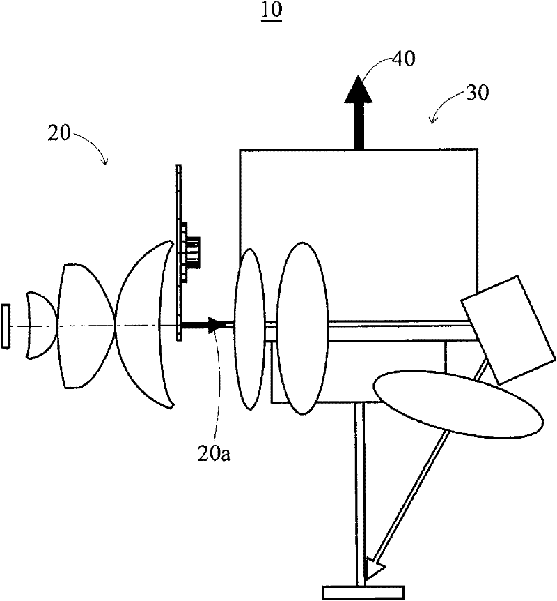
[0014] Such as figure 1 As shown, the projection device 10 of the present invention includes a light source system 20 and an imaging system 30 . Wherein, the light source system 20 of the present invention is used to output an output light source 20a, and devices such as a digital micromirror device (Digital Micromirror Device, DMD) can be used in the imaging system 30 to form an image 40 after receiving and processing the output light source 20a , and project the image 40 to the outside world.

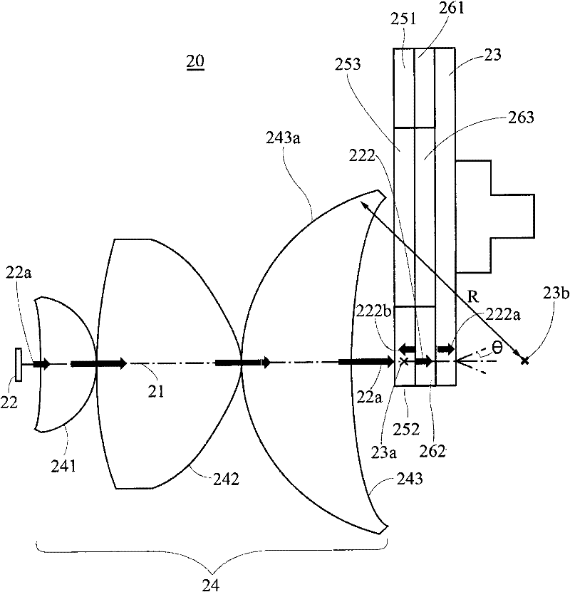
[0015] Such as Figure 2A As shown, the light source system 20 of the present invention at least includes a main optical axis 21 , a light source 22 , a wheel body 23 , an optical device 24 , a first wavelength conversion body 251 and a first angle selection layer 261 . A light beam 22a provided by the light source 22 can advance along the main optical axis 21, and the wheel body 23 rotates according to the control. The optical device 24 has a first lens 241, a second lens 242 and ...


PUM


Abstract

The invention relates to a light source system and a projection device. The projection device comprises the light source system. The light source system comprises a primary optical axis, a light source, a wheel body, an optical device, a first wavelength converter and a first angle selecting layer. The light source can provide a light beam to advance along the primary optical axis. The wheel body can rotate according to control. The optical device is provided with a first lens, a second lens and a third lens which are sequentially arranged between the light source and the wheel body along the primary optical axis to gather the light beam to a focusing position on the wheel body. The first wavelength converter is arranged on the wheel body for receiving and converting the light beam into a first waveband light. The first angle selecting layer selectively filters and passes the first waveband light at an angle and is arranged on the first wavelength converter. The first wavelength converter is positioned between the light source and the first angle selecting layer.

Description

technical field [0001] The present invention relates to a light source system, in particular to a light source system used in a projection device. Background technique [0002] Due to the advantages of light emitting diode (Light Emitting Diode, LED) with high energy conversion efficiency, high stability, long service life, and instant switching, it gradually replaces ultra high pressure mercury bulb (Ultra High Performance, UHP) as a projection lamp. Trends in light sources for installations. When a light emitting diode is used as a light source of a projection device, in order to obtain better light utilization and light distribution uniformity, it is necessary to consider the design and configuration of its internal optical elements. Among them, one of the more common ways is to directly use red, blue, and green light-emitting diodes as the light source of the projection device, and output them after combining light. However, since the luminous efficiency of green LEDs ...

Claims


Application Information

Patent Timeline
IPC IPC(8): G03B21/20G02B27/18F21V13/00F21Y101/02
Inventor 黄俊杰
Owner DELTA ELECTRONICS INC
Why Eureka
Try Eureka